Kia Stinger CK: Steering System / Steering Column & Shaft
Components and components location
| Components |
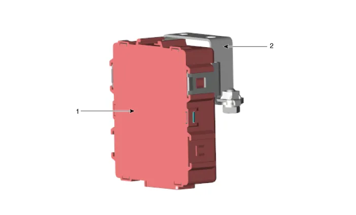
| 1. Steering column module (SCM)
|
2. Steering column module (SCM)
bracket |
Specifications
| Specification |
|
Item |
Specifications |
|
Rated Voltage |
DC 12 V |
|
Operating Voltage Range |
DC 9 - 16 V |
|
Operating Temperature Range |
-30°C ~ +75°C |
|
Storage Temperature Range |
-40°C ~ +85°C |
|
Dark Current |
Max. 1 mA |
Description and operation
| Description |
ptimal steering column position on the tilt & telescope units and reproduce the steering column position when the position has changed.
Reproduction of steering column position is prohibited while driving due to safety reasons. There is an emergency stop function that stops the reproduction and related operations. The following functions are provided.
| 1. |
Manual Operation
|
| 2. |
Memory Function
|
| 3. |
Memory/Reproduction using the smart key: You can use the smart key to memorize and reproduce steering wheel positions for up to 2 people. |
| 4. |
Automatic tilt and telescope position adjustment: Tilt and telescope position can be adjusted automatically based on the key in/out data (CAN data from BCM). |
Schematic diagrams
| Schematic Diagrams |
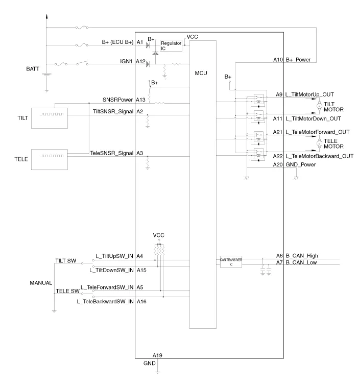
| Terminal Function |

|
Pin No |
Description |
Pin No |
Description |
|
1 |
B + |
12 |
IG 1 |
|
2 |
Tilt sensor input |
13 |
Position sensor power output |
|
3 |
Tele sensor input |
14 |
- |
|
4 |
Tilit up switch input |
15 |
Tilt down switch input |
|
5 |
Tele forward direction switch input |
16 |
Tele bakcward direction switch input |
|
6 |
CAN High |
17 |
- |
|
7 |
CAN Low |
18 |
- |
|
8 |
- |
19 |
Ground |
|
9 |
Tilt motor up output |
20 |
Ground power |
|
10 |
Battery + |
21 |
Tele motor forward direction output |
|
11 |
Tilt motor down output |
22 |
Tele motor backward direction output |
Repair procedures
| Removal |
Steering column module (SCM)
| 1. |
Turn ignition switch OFF and disconnect the negative (-) battery cable. |
| 2. |
Remove the crash pad lower panel. (Refer to Body -"Crash pad lower panel") |
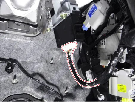
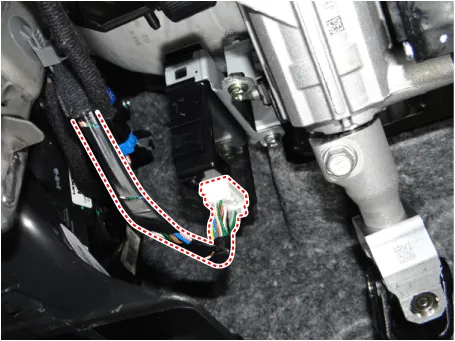
| 3. |
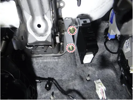
Disconnect the steering column module connector. [LHD]
[RHD]
|
| 4. |
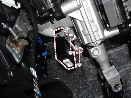
Loosen the steering column module bracket bolts and then remove the steering column module. [LHD]
[RHD]
|
| 5. |
Install in the reverse order of removal. |
Steering column module (SCM) switch
| 1. |
Turn ignition switch OFF and disconnect the negative (-) battery cable. |
| 2. |
Remove the crash pad lower panel. (Refer to Body -"Crash pad lower panel") |
| 3. |
Disconnect the steering column module connector. (Refer to Body -"Steering Column Shroud Panel") |
| 4. |
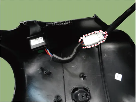
Disconnect the steering module switch connector and clip.
|
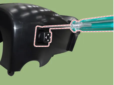
| 5. |
Using the driver, remove the steering column module switch.
|
| 6. |
Install in the reverse order of removal. |
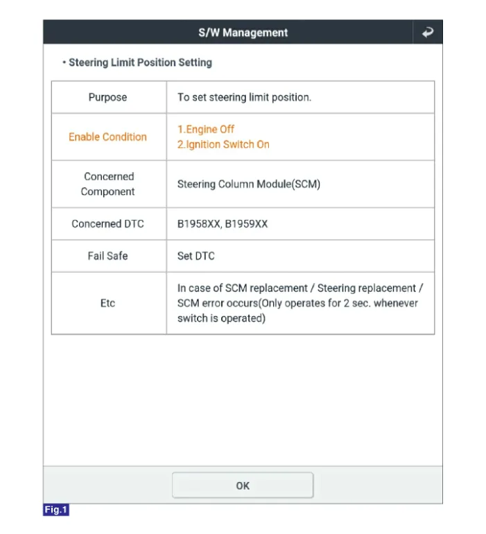
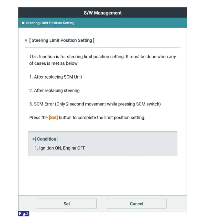
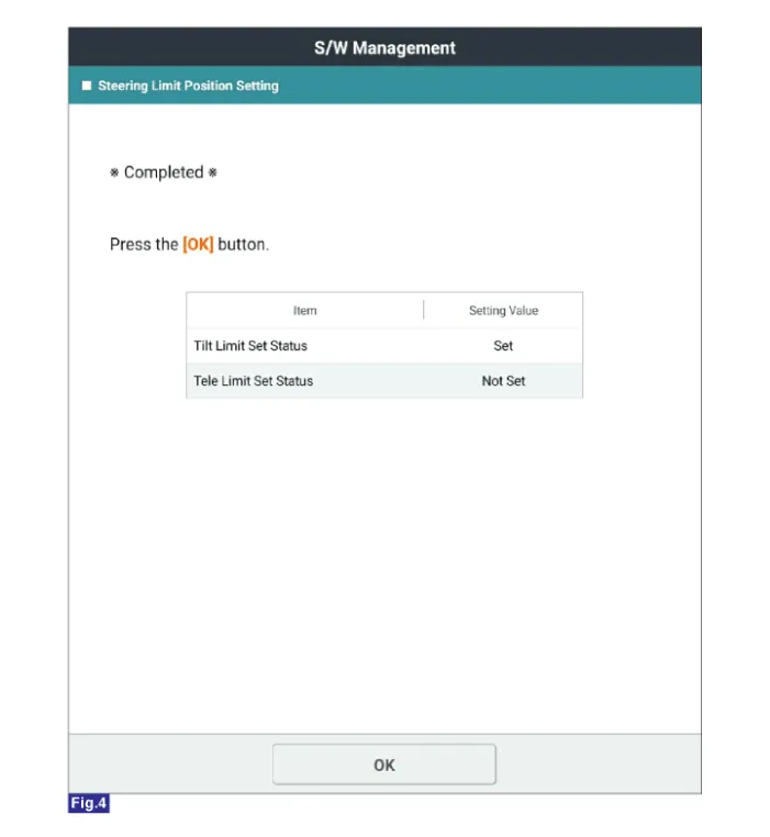
Steering Limit Position Setting
|

| 1. |
Perform the "Steering Limit Position Setting" using the KDS.
|


Other information:
Kia Stinger (CK) 2018-2023 Service Manual: Storage compartments
These compartments can be used to store small items required by the driver or passengers. To avoid possible theft, do not leave valuables in the storage compartment. Always keep the storage compartment covers closed while driving. Do not attempt to place so many items in the storage compartment that the storage compartment cover can not close securely.Components and components location Components [Standard] 1. Caliper housing 2. Brake member 3. Brake pad assembly [IN] 4. Retainer 5. Brake pad assembly [OUT] 6. Brake pad return spring [Brembo] 1. Caliper housing 2. Brake pad cover 3. Brake pad 4.Categories
- Manuals Home
- Kia Stinger Owners Manual
- Kia Stinger Service Manual
- New on site
- Most important about car
