Kia Stinger CK: Cylinder Head Assembly / Cylinder Head Cover
Repair procedures
| Removal |
|

Mark all wiring and hoses to avoid misconnection. |

| 1. |
Disconnect the battery negative terminal. |
| 2. |
Remove the engine cover. (Refer to Engine and Transmission Assembly - "Engine Cover") |
| 3. |
Disconnect the wiring connectors and harness clamps and remove the connector brackets around the cylinder head cover.
|
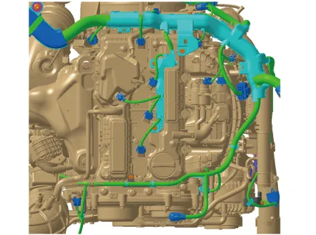
| 4. |
Remove the ignition coils. (Refer to Engine Electrical System - “Ignition Coil”) |
| 5. |
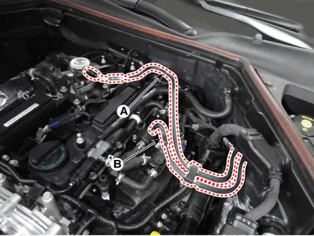
Disconnect the fuel hose (A) and PCSV (Purge control solenoid valve) hose (B).
|
| 6. |
Remove the high pressure fuel pump. (Refer to Engine Control/Fuel System - "High Pressure Fuel Pump") |
| 7. |
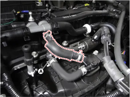
Disconnect the positive crankcase ventilation (PCV) hose (A).
|
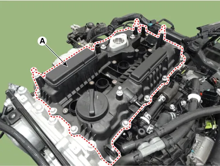
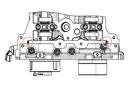
| 8. |
Remove the cylinder head cover (A).
|
| Installation |
| 1. |
Install cylinder head cover.
|

| 2. |
Install the other parts in the reverse order of removal. |


Other information:
Kia Stinger (CK) 2018-2023 Service Manual: Brake Booster Vacuum Pressure Sensor
Description and operation Description In order to ensure adequate brake power assistance in every situation, the brake booster is equipped with a partial vacuum sensor. The brake booster vacuum pressure sensor is located beside the brake booster. Schematic diagrams Circuit Diagram Repair procedures Inspection 1.Kia Stinger (CK) 2018-2023 Service Manual: Blind-spot Collision Warning (BCW)
The Blind-Spot Collision Warning (BCW) system uses radar sensors in the rear bumper to monitor and warn the driver of an approaching vehicle in the driver's blind spot area. The system monitors the rear area of the vehicle and provides information to the driver with an audible alert and a indicator on the outside rearview mirrors. (1) Blind spot area The BCW range varies relative to vehicle speed.Categories
- Manuals Home
- Kia Stinger Owners Manual
- Kia Stinger Service Manual
- New on site
- Most important about car
