Kia Stinger CK: Intake And Exhaust System / Intercooler
Components and components location
| Components |
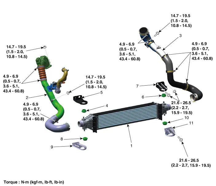
| 1. Intercooler 2. Intercooler inlet hose & pipe 3. Intercooler outlet hose & pipe 4. Intercooler upper mounting insulator (RH) 5. Intercooler upper mounting bracket (RH) 6. Intercooler upper mounting insulator (LH) |
7. Intercooler upper mounting
bracket (LH) 8. Intercooler lower mounting insulator (RH) 9. Intercooler lower mounting bracket (RH) 10. Intercooler lower mounting insulator (LH) 11. Intercooler lower mounting bracket (LH) |
Repair procedures
| Removal and Installation |
Intercooler Inlet Hose & Pipe
| 1. |
Remove the air intake hose. (Refer to Intake and Exhaust System - "Air Cleaner") |
| 2. |
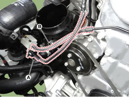
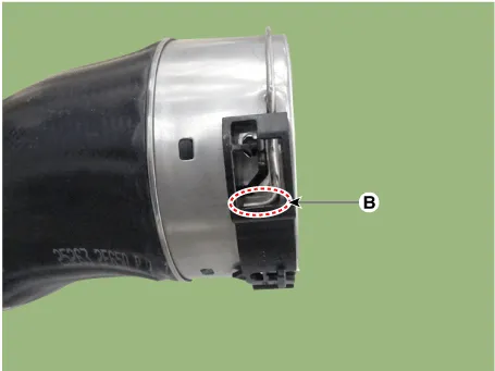
Disconnect the recirculation valve connector (A) and the vacuum hose (B).
|
| 3. |
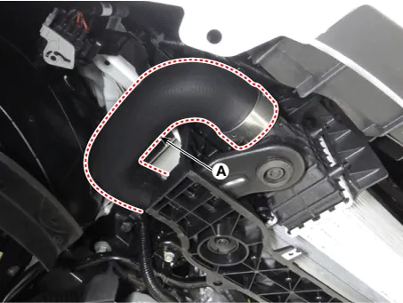
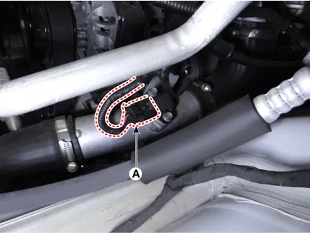
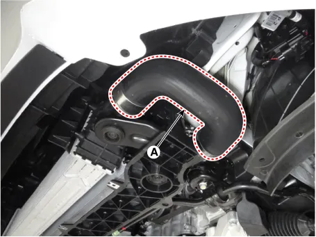
Remove the intercooler inlet hose & pipe assembly (A).
|

| 4. |
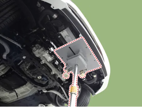
Remove the engine room front under cover. (Refer to Engine and Transmission Assembly - "Engine Room Under Cover") |
| 5. |
Remove the intercooler inlet hose (A).
|

| 6. |
Install in the reverse order of removal. |
Intercooler outlet Hose & Pipe
| 1. |
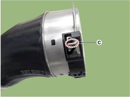
Disconnect the booster pressure sensor connector (A).
|
| 2. |
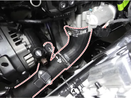
Remove the intercooler outlet hose & pipe assembly (A).
|
| 3. |
Remove the engine room front under cover. (Refer to Engine and Transmission Assembly - "Engine Room Under Cover") |
| 4. |
Remove the intercooler outlet hose (A).
|
| 5. |
Install in the reverse order of removal. |
Intercooler
| 1. |
Remove the engine room front under cover. (Refer to Engine and Transmission Assembly - "Engine Room Under Cover") |
| 2. |
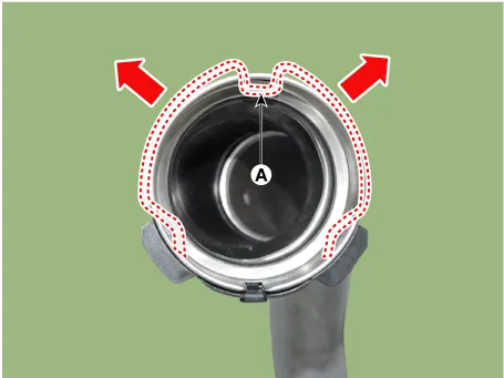
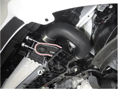
Disconnect the intercooler inlet hose (A).
|
| 3. |
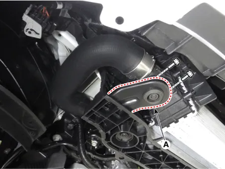
Disconnect the intercooler outlet hose (A).
|
| 4. |
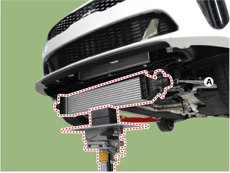
Install the jack under the intercooler to support the intercooler.
|
| 5. |
Remove the intercooler lower mounting bracket (A).
[LH]
[RH]
|
| 6. |
Remove the intercooler (A).
|
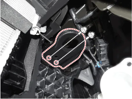
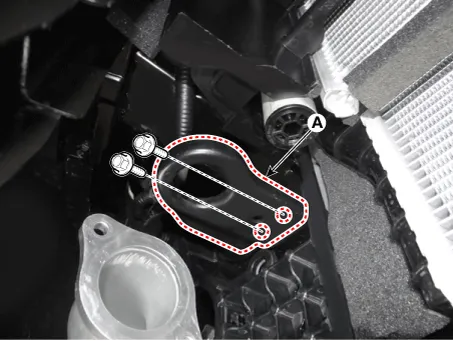
| 7. |
Remove the intercooler upper mounting bracket (A).
[LH]
[RH]
|
| 8. |
Install in the reverse order of removal. |


Other information:
Kia Stinger (CK) 2018-2023 Service Manual: Corrosion protection
Protecting your vehicle from corrosion By using the most advanced design and construction practices to combat corrosion, we produce vehicles of the highest quality. However, this is only part of the job. To achieve the long-term corrosion resistance your vehicle can deliver, the owner's cooperation and assistance is also required. Common causes of corrosion The most common causes of corrosion on your vehicle are: Road salt, dirt and moisture that is allowed to accumulate underneath the vehicle.Kia Stinger (CK) 2018-2023 Service Manual: Snowy or icy conditions
To drive your vehicle in deep snow, it may be necessary to use Snow tires on your tires. If snow tires are needed, it is necessary to select tires equivalent in size and type of the original equipment tires. Failure to do so may adversely affect the safety and handling of your vehicle. Furthermore, speeding, rapid acceleration, sudden brake applications, and sharp turns are potentially very hazardous practices.Categories
- Manuals Home
- Kia Stinger Owners Manual
- Kia Stinger Service Manual
- New on site
- Most important about car
