Kia Stinger CK: Intake And Exhaust System / Intake Manifold
Components and components location
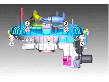
| Components |
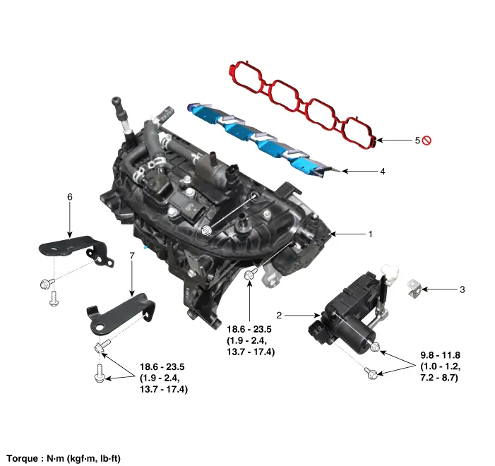
| 1. Intake manifold 2. VCM actuator 3. Clip 4. VCM shaft |
5. Intake manifold gasket 6. Intake manifold bracket (LH) 7. Intake manifold bracket (RH) |
Repair procedures
| Removal and Installation |
| 1. |
Disconnect the negative battery terminal. |
| 2. |
Remove the engine room front under cover. (Refer to Engine and Transmission Assembly - "Engine Room Under Cover") |
| 3. |
Drain the coolant. (Refer to Cooling System - "Coolant") |
| 4. |
Remove the engine cover. (Refer to Engine and Transmission Assembly - "Engine Cover") |
| 5. |
Disconnect the wiring connectors and harness clamps and remove the connector brackets around the intake manifold.
|
| 6. |
Disconnect the radiator upper hose (A) and water hose (B).
|
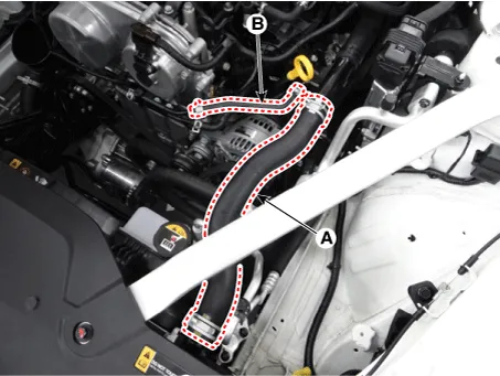
| 7. |
Remove the water outlet pipe assembly (A).
|
| 8. |
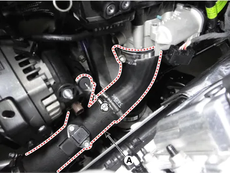
Remove the intercooler outlet hose & pipe assembly (A).
|
| 9. |
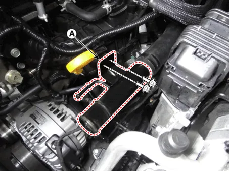
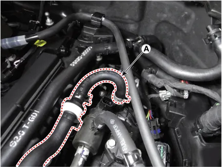
Disconnect the positive crankcase ventilation (PCV) hose (A).
|
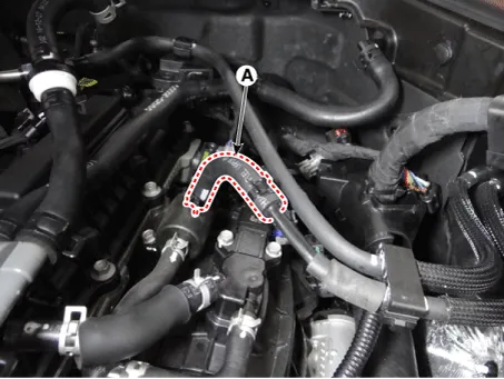
| 10. |
Disconnect the purge control solenoid valve (PCSV) hose (A).
|
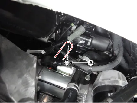
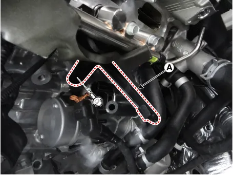
| 11. |
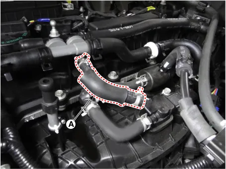
Disconnect the vacuum hose (A).
|
| 12. |
Remove the alternator. (Refer to Engine Electrical System - "Alternator") |
| 13. |
Unfasten the electric throttle body control (ETC) module bolts. (Refer to Engine Control / Fuel System - "Electric Throttle Body Control System (ETC)") |
| 14. |
Remove the oil level pipe. (Refer to Lubrication System - "Oil Level Gauge & Pipe") |
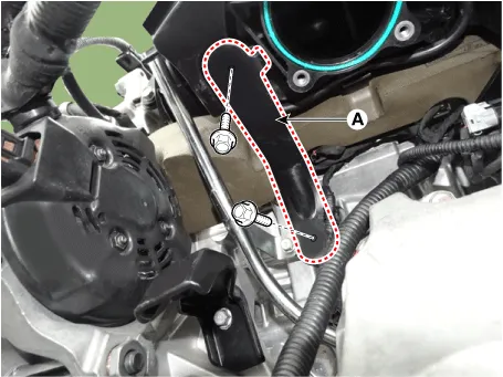
| 15. |
Remove the intake manifold stay (A).
|
| 16. |
Remove the intake manifold stay bolt (A).
|
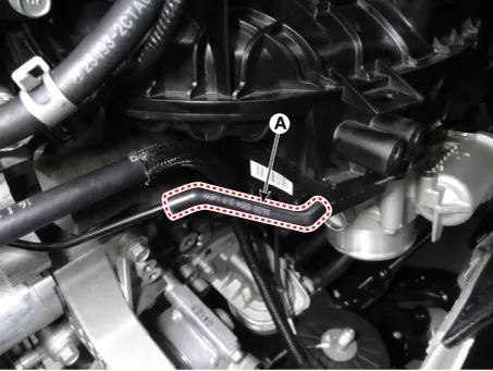
| 17. |
Disconnect the vacuum hose (A).
|
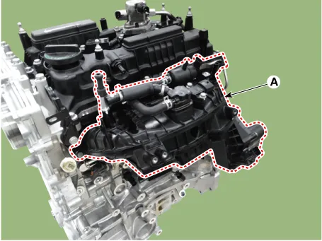
| 18. |
Remove the intake manifold (A).
|
| 19. |
Remove the intake manifold stay (A).
|
| 20. |
Install in the reverse order of removal.
|


Other information:
Kia Stinger (CK) 2018-2023 Service Manual: Engine Oil and Filter
Repair procedures Inspection [Theta-II 2.0 T-GDI / Lambda-II 3.3 T-GDI] Engine Oil Level Be sure that the vehicle is on level ground. 1. Warm up and stop the engine, and then wait for 5 minutes. 2. Turn the engine off and wait for a few minutes (about 5 minutes) for the oil to return to the oil pan.Components and components location Components Connector Pin Information No. Connector A Connector B Connector C Connector D 1 Rear door left speaker (+) ⁻ ⁻ Ground 2 Rear door left speaker (-) MIC (+) ⁻ ⁻ 3 ⁻ ⁻ ⁻Categories
- Manuals Home
- Kia Stinger Owners Manual
- Kia Stinger Service Manual
- New on site
- Most important about car
