Kia Stinger CK: Intake And Exhaust System / Intercooler
Components and components location
| Components |
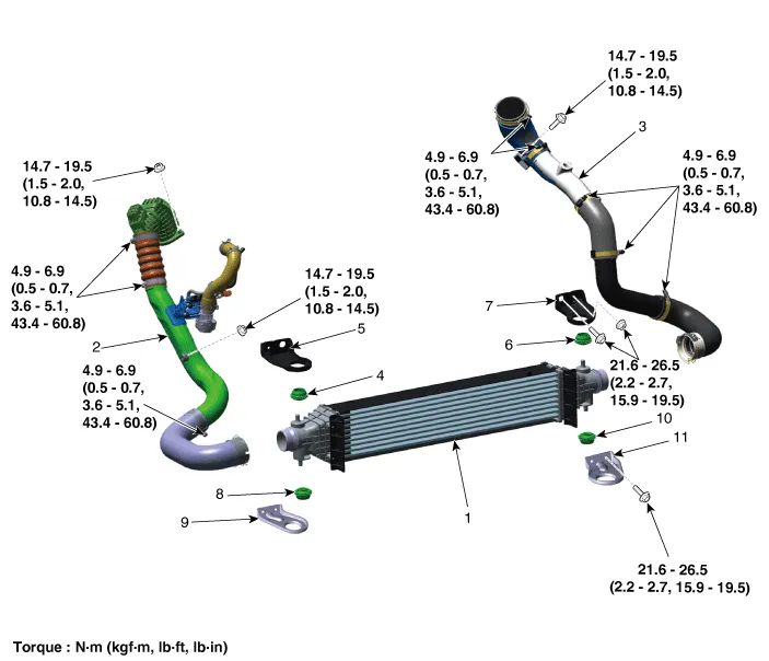
| 1. Intercooler 2. Intercooler inlet hose & pipe 3. Intercooler outlet hose & pipe 4. Intercooler upper mounting insulator (RH) 5. Intercooler upper mounting bracket (RH) 6. Intercooler upper mounting insulator (LH) |
7. Intercooler upper mounting
bracket (LH) 8. Intercooler lower mounting insulator (RH) 9. Intercooler lower mounting bracket (RH) 10. Intercooler lower mounting insulator (LH) 11. Intercooler lower mounting bracket (LH) |
Repair procedures
| Removal and Installation |
Intercooler Inlet Hose & Pipe
| 1. |
Remove the air intake hose. (Refer to Intake and Exhaust System - "Air Cleaner") |
| 2. |
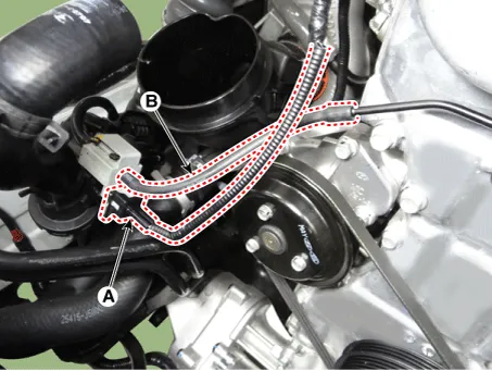
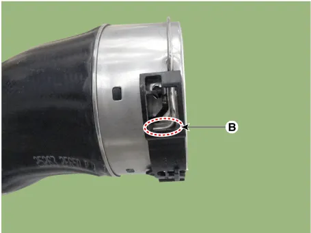
Disconnect the recirculation valve connector (A) and the vacuum hose (B).
|
| 3. |
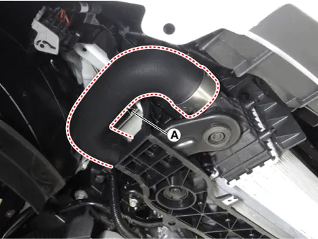
Remove the intercooler inlet hose & pipe assembly (A).
|

| 4. |
Remove the engine room front under cover. (Refer to Engine and Transmission Assembly - "Engine Room Under Cover") |
| 5. |
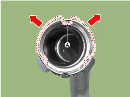
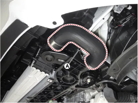
Remove the intercooler inlet hose (A).
|

| 6. |
Install in the reverse order of removal. |
Intercooler outlet Hose & Pipe
| 1. |
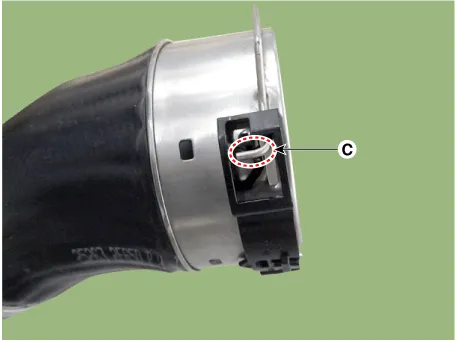
Disconnect the booster pressure sensor connector (A).
|
| 2. |
Remove the intercooler outlet hose & pipe assembly (A).
|
| 3. |
Remove the engine room front under cover. (Refer to Engine and Transmission Assembly - "Engine Room Under Cover") |
| 4. |
Remove the intercooler outlet hose (A).
|
| 5. |
Install in the reverse order of removal. |
Intercooler
| 1. |
Remove the engine room front under cover. (Refer to Engine and Transmission Assembly - "Engine Room Under Cover") |
| 2. |
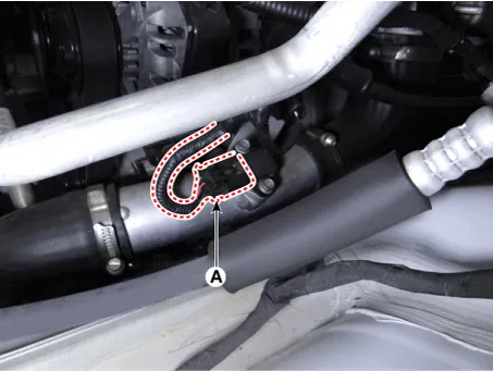
Disconnect the intercooler inlet hose (A).
|
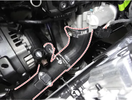
| 3. |
Disconnect the intercooler outlet hose (A).
|
| 4. |
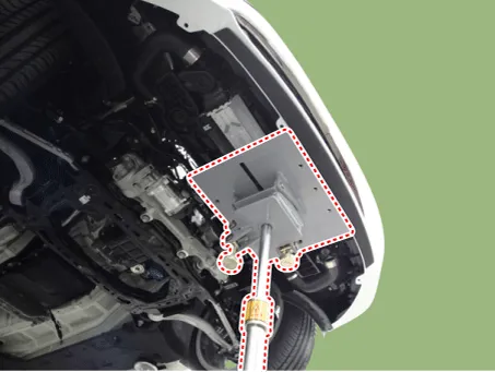
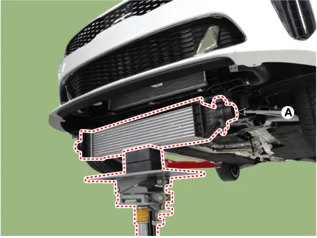
Install the jack under the intercooler to support the intercooler.
|
| 5. |
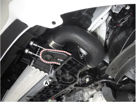
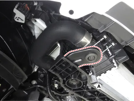
Remove the intercooler lower mounting bracket (A).
[LH]
[RH]
|
| 6. |
Remove the intercooler (A).
|
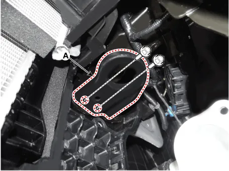
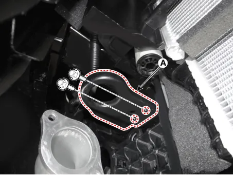
| 7. |
Remove the intercooler upper mounting bracket (A).
[LH]
[RH]
|
| 8. |
Install in the reverse order of removal. |


Other information:
Description and operation Description The starting system includes the battery, starter, solenoid switch, ignition switch, inhibitor switch (A/T), clutch pedal switch (M/T), ignition lock switch, connection wires and the battery cable. When the ignition key is turned to the start position, current flows and energizes the starter motor's solenoid coil.Components and components location Components Connector Pin Information No. Connector A Connector B Connector C Connector D 1 Rear door left speaker (+) ⁻ ⁻ Ground 2 Rear door left speaker (-) MIC (+) ⁻ ⁻ 3 ⁻ ⁻ ⁻Categories
- Manuals Home
- Kia Stinger Owners Manual
- Kia Stinger Service Manual
- New on site
- Most important about car
