Kia Stinger CK: Driving your vehicle / Drive mode integrated control system
The drive mode may be selected according to the driver's preference or road condition.
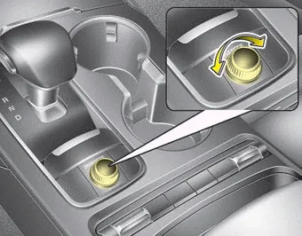
The mode changes whenever the DRIVE MODE button is turned.
- SMART mode : SMART mode automatically adjusts the driving mode (ECO ↔ COMFORT ↔ SPORT) in accordance with the driver's driving habits.
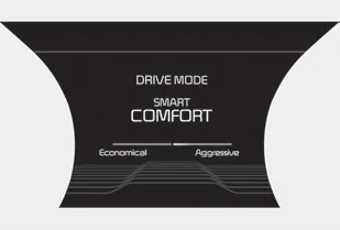
- COMFORT mode : COMFORT mode provides smooth driving and a comfortable ride.
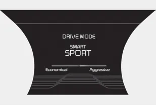
- SPORT mode : SPORT mode provides a sporty but firm ride.
- CUSTOM mode : CUSTOM mode allows the driver to mix aspects of other driving modes to make a customized mode.
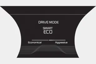
- ECO mode : ECO mode improves fuel efficiency for eco-friendly driving.
If it is in ECO mode, ECO mode will be set when the engine is restarted. (However, if it is in SMART/COMFORT/ SPORT/CUSTOM mode, the drivie mode will be set to COMFORT mode when the engine is restarted.)
SMART mode

SMART mode selects the proper drive mode among ECO, COMFORT and SPORT by judging the driver's driving habits (i.e. mild or dynamic) from the brake pedal depression or the steering wheel operation.
• Rotate the DRIVE MODE dial knob to activate SMART mode. When SMART mode is activated, the indicator illuminates on the instrument cluster. • The indicator illuminates in blue, when the driver's driving is categorized to be mild. It illuminates in white, when the driver's driving is categorized to be normal. It illuminates in red, when the driver's driving is categorized to be dynamic during abrupt braking or sharp curves. • The vehicle starts in COMFORT mode, if the engine was turned OFF in SMART mode. • SMART mode automatically controls the vehicle’s characteristics, such as gear shifting patterns, engine torque, ride quality (if equipped with the electronic suspension system), and power distribution (if equipped with the All- Wheel Drive (AWD) system), in accordance with the driver's driving habits.
mode, if the engine was turned OFF in SMART mode. • SMART mode automatically controls the vehicle’s characteristics, such as gear shifting patterns, engine torque, ride quality (if equipped with the electronic suspension system), and power distribution (if equipped with the All- Wheel Drive (AWD) system), in accordance with the driver's driving habits.
✽ NOTICE
- When you mildly drive the vehicle in SMART mode, the drive mode changes to ECO mode to improve fuel efficiency. However, the actual fuel efficiency may differ in accordance with your driving situations (i.e. upward/downward slope, vehicle deceleration/acceleration).
- When you dynamically drive the vehicle in SMART mode by abruptly decelerating or sharply turning, the drive mode changes to SPORT mode. However, it may adversely affect fuel economy.
Various driving situations, which you may encounter in SMART mode
- The drivie mode automatically changes to ECO mode after a certain period of time, when you gently depress the accelerator pedal (Your driving is categorized to be mild.).
- The drive mode automatically changes from SMART ECO mode to SMART COMFORT mode after a certain period of time, when you sharply or repetitively depress the accelerator pedal.
- The drive mode automatically changes to SMART COMFORT mode with the same driving patterns, when the vehicle starts to drive on an upward slope of a certain angle. The drive mode automatically returns to SMART ECO mode, when the vehicle enters a leveled road.
- The drive mode automatically changes to SMART SPORT, when you abruptly accelerate the vehicle or repetitively operate the steering wheel (Your driving is categorized to be sporty.). In this mode, your vehicle drives in a lower gear for abrupt accelerating/decelerating and increases the engine brake performance.
- You may still sense the engine brake performance, even when you release the accelerator pedal in SMART SPORT mode. It is because your vehicle remains in a lower gear over a certain period of time.
- The drive mode automatically changes to SMART SPORT mode only in dynamic driving situations. In most of the normal driving situations, the drive mode sets to be either in SMART ECO mode or in SMART COMFORT mode.
Limitation of SMART mode
The SMART mode may be limited in following situations. (The OFF indicator illuminates in those situations.)
- The driver manually moves the shift lever : It deactivates SMART mode.
- The cruise control is activated : The cruise system may deactivate the SMART mode. (SMART mode is not automatically deactivated just by activing the cruise system.)
- The transmission oil temperature is either extremely low or extremely high : The SMART mode can be active in most of the normal driving situations. However, an extremely high/ low transmission oil temperature may temporarily deactivate the SMART mode, because the transmission condition is out of normal operation condition.
SPORT mode

SPORT mode manages the driving dynamics by automatically adjusting the steering effort, and the engine and transmission control logic for enhanced driver performance.
- When SPORT mode is selected by pressing the DRIVE MODE button, the SPORT indicator (orange color) will illuminate.
- Whenever the engine is restarted, the Drive Mode will revert back to COMFORT mode. If SPORT mode is desired, re-select SPORT mode from the DRIVE MODE button.
- When SPORT mode is activated:
- The engine rpm will tend to remain raised over a certain length of time even after releasing the accelerator
- Upshifts are delayed when accelerating
✽ NOTICE
In SPORT mode, the fuel efficiency may decrease.
CUSTOM mode

CUSTOM mode enables driver to build their own customized mode. Driver can choose between different Engine/Transmission, Steering, Suspension, AWD, and Active Engine Sound settings.
- To access CUSTOM mode settings rotate the Drive Mode knob until getting to CUSTOM mode. A Graphic picture of Kia Stinger will pop up on main screen with a setting button. Press the setting button and change different settings to build your own mode.
- Once the CUSTOM mode settings are chosen they will be saved and will remain that way until changed again in settings.
- Whenever the engine is restarted, the Drive Mode will revert back to COMFORT mode. If CUSTOM mode is desired, re-select CUSTOM mode from the DRIVE MODE button.
ECO mode

When the Drive Mode is set to ECO mode, the engine and transmission control logic are changed to maximize fuel efficiency.
- When ECO mode is selected by pressing the DRIVE MODE button, the ECO indicator (green color) will illuminate.
- If the vehicle is set to ECO mode, when the engine is turned OFF and restarted the Drive Mode setting will remain in ECO mode.
✽ NOTICE
Fuel efficiency depends on the driver's driving habits and road condition.
When ECO mode is activated:
- The acceleration response may be slightly reduced if the accelerator pedal is depressed moderately.
- The air conditioner performance may be limited.
- The shift pattern of the automatic transmission may change.
- The engine noise may get louder.
The above situations are normal conditions when ECO mode is activated to improve fuel efficiency.
Limitation of ECO mode operation:
If the following conditions occur while ECO mode is operating, the system operation is limited even though there is no change in the ECO indicator.
- When the coolant temperature is low: The system will be limited until engine performance becomes normal.
- When driving up a hill: The system will be limited to gain power when driving uphill because engine torque is restricted.
- When driving the vehicle with the automatic transmission gear shift lever in manual mode. The system will be limited according to the shift location.


Other information:
Kia Stinger (CK) 2018-2023 Owner's Manual: Front Door Outside Handle
Components and components location Component Location 1. Front door outside handle Repair procedures Replacement Put on gloves to protect your hands. • When prying with a flat-tip screwdriver or using a prying trim tool, wrap protective tap around the tool and related parts to prevent damage.Repair procedures Removal 1. Disconnect the negative (-) battery terminal. 2. Remove the vanity lamp (A) using a flat-tip screwdriver. 3. Disconnect the vanity lamp connector (A). Installation 1. Connect the vanity lamp connector.Categories
- Manuals Home
- Kia Stinger Owners Manual
- Kia Stinger Service Manual
- New on site
- Most important about car
