Kia Stinger CK: ISG (Idle Stop and Go) system / ISG system malfunction
Contents:
The system may not operate when:
The system may not operate when an ISG related sensor or system error occurs.
The following will happen:
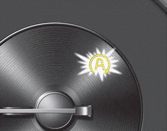
- The yellow AUTO STOP (
 ) indicator
on the instrument cluster will stay on after blinking for 5 seconds.
) indicator
on the instrument cluster will stay on after blinking for 5 seconds. - The light on the ISG OFF button will illuminate.
✽ NOTICE
If the ISG OFF button light is not turned off by pressing the ISG OFF button again or if the ISG system continuously does not work correctly, have your vehicle inspected by an authorized Kia dealer.
When the engine is in Idle Stop mode, it's possible to restart the engine without the driver taking any action. Before leaving the car or doing anything in the engine compartment, stop the engine by turning the ignition switch to the LOCK/OFF position or removing the ignition key.
✽ NOTICE
If the AGM battery is reconnected or replaced, ISG function will not operate immediately. If you want to use the ISG function, the battery sensor needs to be calibrated for approximately 4 hours with the ignition off. After calibration, turn the engine on and off 2 or 3 times.


Other information:
Kia Stinger (CK) 2018-2023 Owner's Manual: Trailing Arm
Repair procedures Removal 1. Remove wheel nuts, wheel and tire (A) from hub. Tightening torque: 107.9 - 127.5 N·m (11.0 - 13.0 kgf·m, 79.6 - 94.0 lb·ft) Be careful not to damage the wheel bolts when removing the wheel and tire (A).Kia Stinger (CK) 2018-2023 Owner's Manual: ESP(Electronic Stability Program) System
Components and components location Components Location 1. HECU module 2. Front wheel speed sensor (2WD) 3. Front wheel speed sensor (AWD) 4. Rear wheel speed sensor Description and operation Description of ESP Electronic Stability Program (ESP) recognizes critical driving conditions, such as panic reactions in dangerous situations, and stabilizes the vehicle by wheel-individual braking and engine control intervention.Categories
- Manuals Home
- Kia Stinger Owners Manual
- Kia Stinger Service Manual
- New on site
- Most important about car
Contents
