Kia Stinger CK: Blind-Spot Collision Warning (BCW) / Blind-Spot Collision Warning (BCW) Radar Calibration
Repair procedures
| Inspection |
Correction Overview
Need to calibrate the mounting angle of the BCW when a vehicle has a rear or a side collision with BCW system even just replacing a BCW bracket or BCW components.
Check before Correction
| 1. |
When a failure code [C2702 (Master)] or [C2703 (Slave)] occurs, check the following before performing correction. |
| 2. |
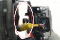
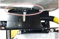
Check the vehicle condition and whether the BCW unit or bracket is deformed (mounting angle, twisted vehicle body, etc.).
|
||||||||||||


| 3. |
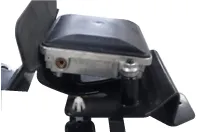
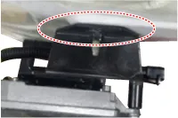
Check the nut tightening. Check if there is any foreign substance.
|
||||||||||||||

Correcting the BCW Angle
| 1. |
After replacing the BCW unit or bracket, with the bumper removed, use the BCW unit correction tool set (special tool : 09958-3T000) to perform angle correction.
|

| 2. |
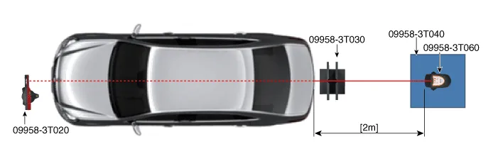
Attach a vertical plumb (special tool : 09958-3T010) on the hood, and lower the plumb (A) to the ground so that it passes through the center of the emblem.
|
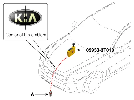
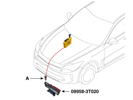
| 3. |
Install an optical receiver (special tool : 09958-3T020) below the plumb (A).
|
| 4. |
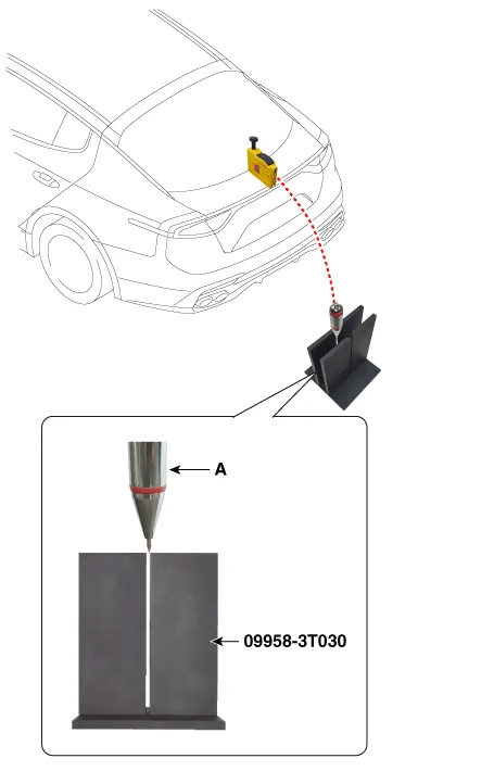
Attach a vertical plumb (special tool : 09958-3T010) on the trunk (or tailgate), and lower the plumb (A) to the ground so that it passes through the center of the emblem.
|
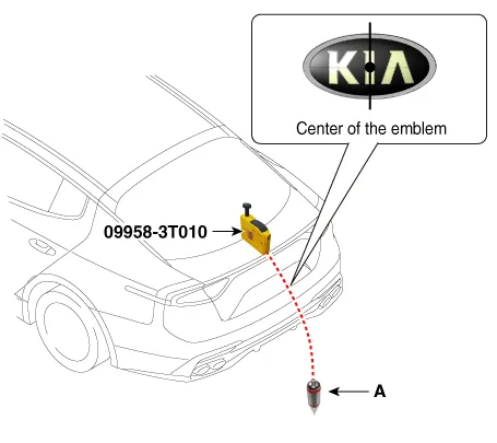
| 5. |
Install the rear setting jig (special tool : 09958-3T030) so that its hole is placed directly under the plumb (A).
|
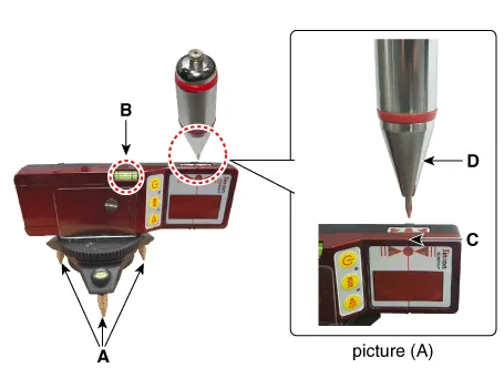
| 6. |
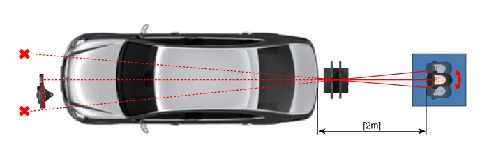
Place the laser support (special tool : 09958-3T040) at a location '2m' away from the rear of the vehicle and install the level laser (special tool : 09958-3T060) above the laser support.
|
| 7. |
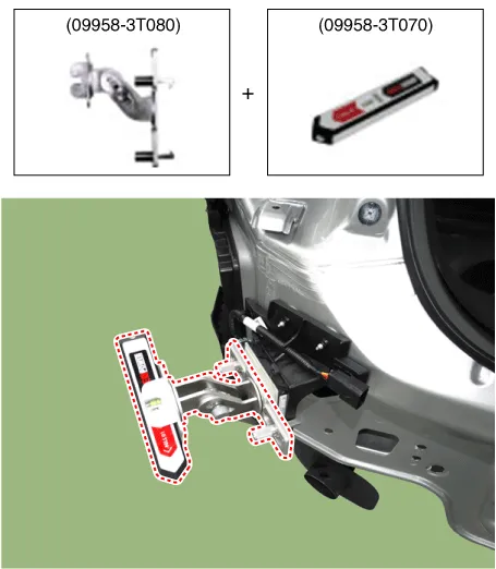
Mount the BCW unit fixing adaptor (special tool : 09958-3T080) on the BCW unit and fix the level laser (special tool : 09958-3T070).
|
| 8. |
Install an angle measuring plate (special tool : 09958-3T050) at a location where the center line laser beam (A) and the horizontal laser beam (B) cross each other.
|

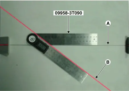
| 9. |
Measure the angle between the center line (A) of the angle measuring plate and the horizontal laser beam (B) using a digital protractor (special tool : 09958-3T090).
|
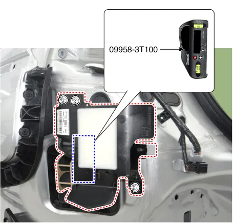
| 10. |
Use a digital inclinometer (special tool : 09958-3T100) to measure the vertical angle of the BCW unit.
|
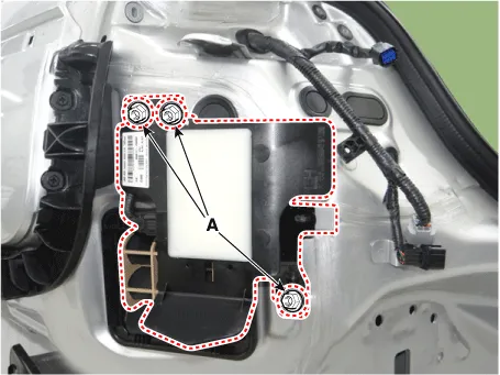
| 11. |
Measure the horizontal and vertical angles of left and right BCW units. If the measured values deviate from the specified values, insert a washer (A) between the bracket of the BCW unit.
|
| 12. |
After checking and correcting the BCW unit angle, perform the BCW radar correction procedure. |
BCW Unit Alignment
| 1. |
Rear bumper accident vehicles and vehicles that replaced BCW units must perform BCW unit alignment using KDS. |
| 2. |
Select "BCW Radar Calibration" procedure in BCW system.
|
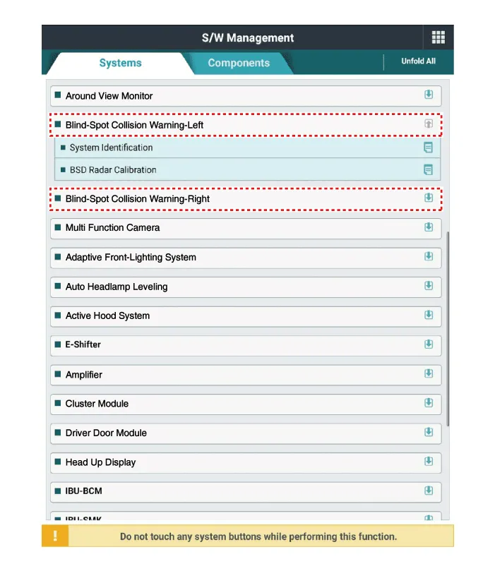

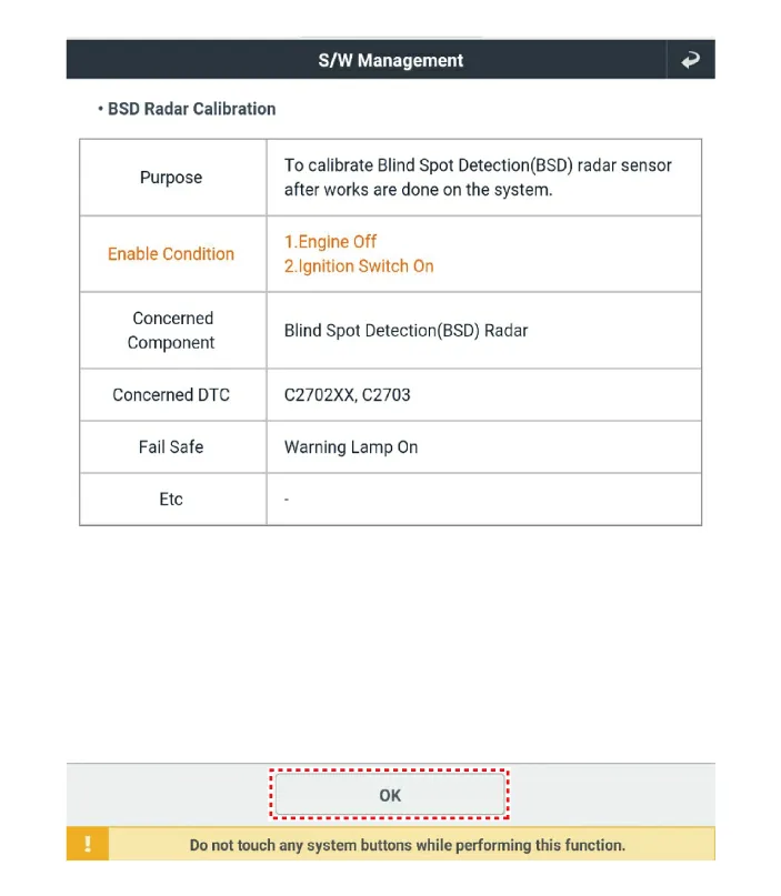
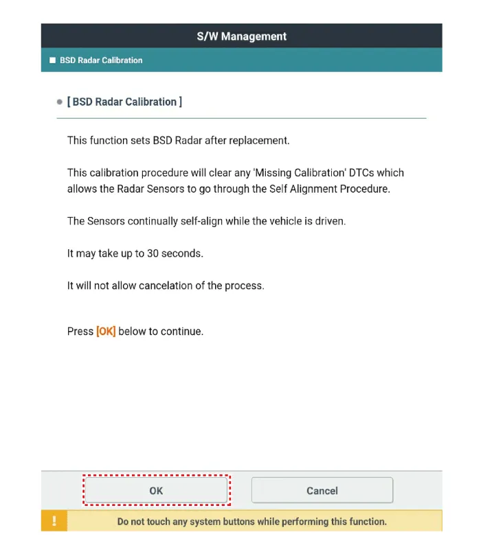
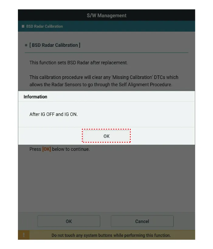
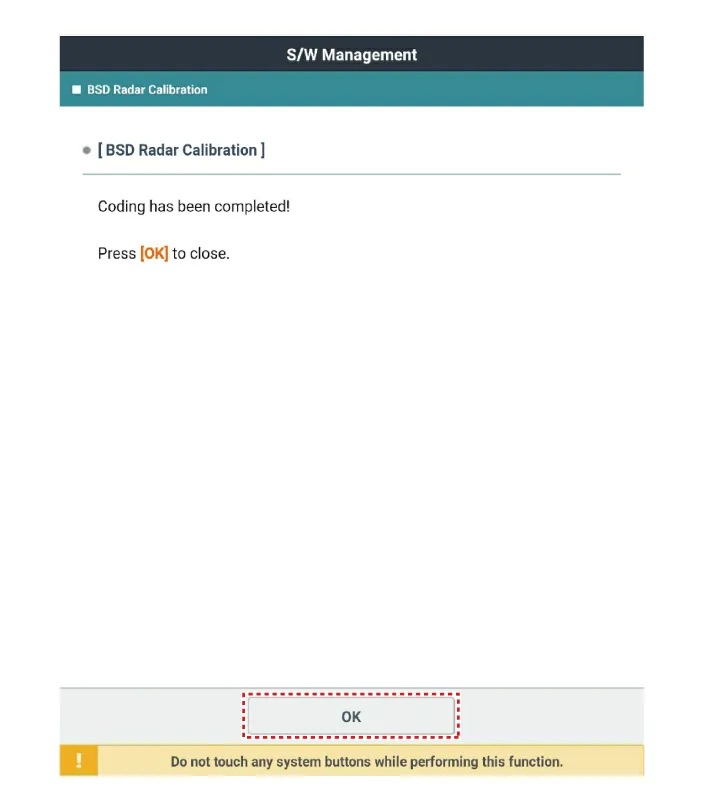
| 3. |
Perform the "BCW Radar Calibration" procedure according to the KDS screen message.
|


Other information:
Kia Stinger (CK) 2018-2023 Service Manual: Bulb replacement precaution
Please keep extra bulbs on hand with appropriate wattage ratings in case of emergencies. Refer to “Bulb Wattage” in chapter 8. When changing lamps, first turn off the engine at a safe place, firmly apply the parking brake and detach the battery’s negative (-) terminal. WARNING - Working on the lights Prior to working on the light, firmly apply the parking brake, ensure that the ignition switch is turned to the LOCK position and turn off the lights to avoid sudden movement of the vehicle burns to your skin or fingers, or an electric shock.Cancelled manually The smart cruise control system is temporarily canceled when the brake pedal is depressed or the CANCEL button is pressed. The speed and vehicle to vehicle distance indicator on the cluster will disappear and the CRUISE indicator is illuminated continuously. Cancelled automatically The driver's door is opened. The shift lever is shifted to N (Neutral), R (Reverse) or P (Parking).Categories
- Manuals Home
- Kia Stinger Owners Manual
- Kia Stinger Service Manual
- New on site
- Most important about car
