Kia Stinger CK: Blind-Spot Collision Warning (BCW) / Blind-Spot Collision Warning (BCW) Switch
Schematic diagrams
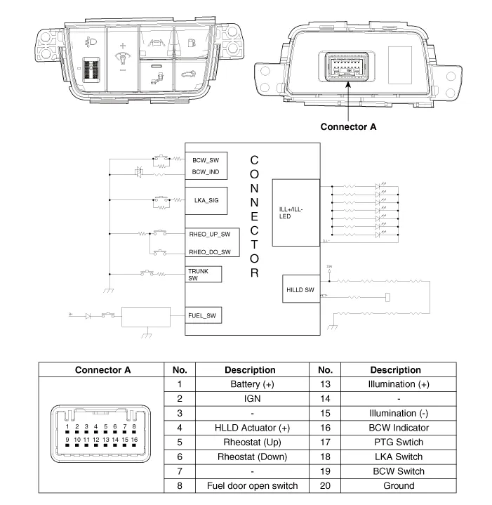
| Circuit Diagram |
Repair procedures
| Removal |
| 1. |
Disconnect the negative (-) battery terminal. |
| 2. |
Remove the crash pad lower panel. (Refer to Body - "Crash Pad Lower Panel") |
| 3. |
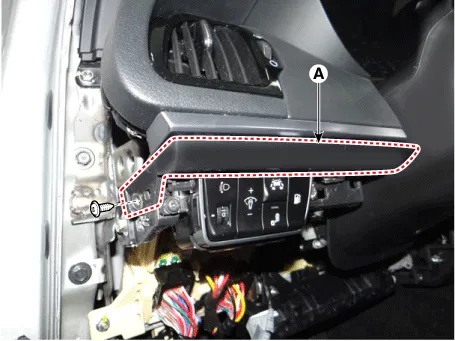
Remove the crash pad garnish [LH] (A) after loosening the mounting screw.
|
| 4. |
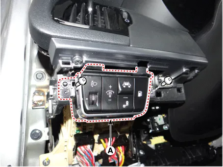
Remove the side crash pad switch (A) after loosening the mounting screws.
|
| 5. |
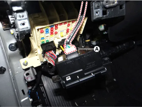
Disconnect the side crash pad switch connector (A).
|
| Installation |
| 1. |
Connect the side crash pad switch connector. |
| 2. |
Install the side crash pad switch. |
| 3. |
Install the crash pad garnish [LH]. |
| 4. |
Install the crash pad lower panel. |
| 5. |
Connect the negative (-) battery terminal. |
| Inspection |
| 1. |
Disconnect the BCW switch connector from the side crash pad switch.
|

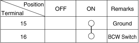
| 2. |
Operate the BCW switch, then check for continuity between terminals and BCW switch connector.
|


Other information:
Kia Stinger (CK) 2018-2023 Service Manual: Engine compartment fuse replacement
1. Turn the ignition switch and all other switches off. 2. Remove the fuse panel cover by pressing the tab and pulling the cover up. When the blade type fuse is disconnected, remove it by using the clip designed for changing fuses located in the engine compartment fuse box. Upon removal, securely insert reserve fuse of the same rating. 3. Check the removed fuse; replace it if it is blown.Components and components location Components 1. Console complete 2. Floor console tray 3. Console upper complete 4. Lever boots 5. Console storage box matCategories
- Manuals Home
- Kia Stinger Owners Manual
- Kia Stinger Service Manual
- New on site
- Most important about car
