Kia Stinger CK: ISG (Idle Stop & Go) System / Brake Booster Vacuum Pressure Sensor
Kia Stinger (CK) 2018-2023 Service Manual / Engine Control / Fuel System / ISG (Idle Stop & Go) System / Brake Booster Vacuum Pressure Sensor
Description and operation
| Description |
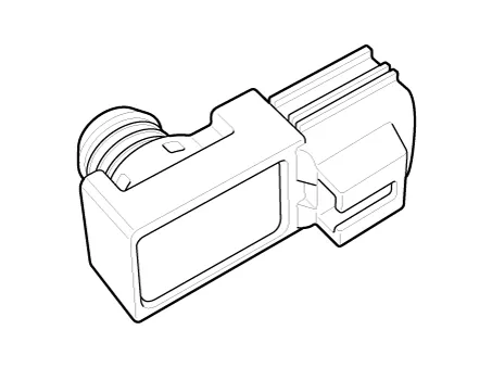
In order to ensure adequate brake power assistance in every situation, the brake booster is equipped with a partial vacuum sensor. The brake booster vacuum pressure sensor is located beside the brake booster.
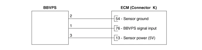
Schematic diagrams
| Circuit Diagram |
Repair procedures
| Inspection |
| 1. |
Check for loose connection of BBCPS and vacuum hose, and damage of vacuum hose. |
| 2. |
Connect KDS to DLC (Data Link Cable). |
| 3. |
Warm up the engine to normal operating temperature. |
| 4. |
Monitor "BBVPS" parameter on KDS. |


Other information:
Kia Stinger (CK) 2018-2023 Service Manual: Rear Oil Seal
Repair procedures Replacement 1. Remove the automatic transmission. (Refer to Automatic Transmission System - "Automatic Transmission") 2. Remove the drive plate. (Refer to Cylinder Block - "Drive Plate") 3. Remove the rear oil seal (A). 4.Kia Stinger (CK) 2018-2023 Service Manual: Outside rearview mirror
Be sure to adjust the mirror angles before driving. Your vehicle is equipped with both left-hand and right-hand outside rearview mirrors. The mirrors can be adjusted remotely with the remote switch. The mirror heads can be folded back to prevent damage during an automatic vehicle wash or when passing through a narrow street. The right outside rearview mirror is convex.Categories
- Manuals Home
- Kia Stinger Owners Manual
- Kia Stinger Service Manual
- New on site
- Most important about car

Copyright © 2026 www.kstinger.com 0.0147