Kia Stinger CK: ISG (Idle Stop & Go) System / Battery sensor
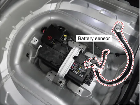
Description and operation
For various control units installed on the vehicle to function based on the signals
from various sensors, stable power supply is essential. ECM controls generating
voltage by duty cycle based on the signals on voltage, current and temperature of
battery from battery sensor mounted to negative (-) battery terminal.
|
In case of battery sensor signal fault, inspect the vehicle parasitic
draw after inspecting the sensor. The sensor may behave abnormally if the
parasitic draw is greater than 100 mA. (Refer to vehicle parasitic current
inspection.)
|
|
Perform the following process after replacing the battery sensor.
| – |
Switch "ON/OFF" the ignition.
|
| – |
Park the vehicle for about 4 hours.
|
| – |
After 4 hours, check the SOC (State of charge) of battery using
KDS.
|
|
|
For a vehicle equipped with a battery sensor, be careful not to damage
the battery sensor when replacing or recharging the battery.
| 1) |
When replacing the battery, always replace with a battery of
the same type, capacity and brand. If a battery of a different type
is installed, the battery sensor may recognize the battery as abnormal.
|
| 2) |
When connecting the ground cable to the negative terminal of
battery, tighten the clamp to the specified torque of 4.0 - 6.0
N.m (0.4 - 0.6 kgf.m, 3.0 - 4.4 lb-ft). An excessive tightening
torque can damage the PCB internal circuit.
|
| 3) |
When recharging the battery, ground the negative terminal of
the booster battery to the vehicle body.
|
|
Repair procedures
| 1. |
Turn the ignition switch OFF.
|
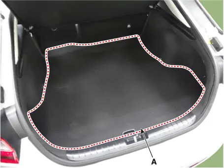
| 2. |
Remove the luggage covering (A).
|
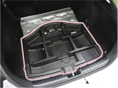
| 3. |
Remove the luggage center tray (A).
|
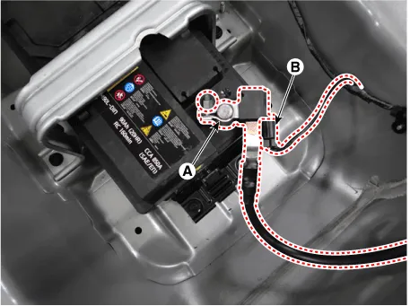
| 4. |
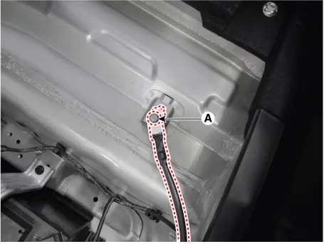
Disconnect the battery negative (-) terminal (A).
|
| 5. |
Disconnect the battery sensor connector (B).
|
| 6. |
Remove the battery sensor by loosening the mounting bolts (C).
|
| 1. |
Install in the reverse order of removal.
| •
|
After reconnecting the negative battery cable, the AMS
and ISG functions will not operate for about 4 hours until
the system is stabilized.
When disconnecting the negative (-) battery cable from
the battery when repairing a vehicle equipped with ISG function,
perform battery sensor recalibration procedure after repairing.
(Refer to Battery Sensor Recalibration Procedure.)
|
|
| •
|
For a vehicle equipped with a battery sensor, be careful
not to damage the battery sensor when replacing or recharging
the battery.
|
| 1) |
When replacing the battery, always replace with a battery
of the same type, capacity and brand. If a battery of a
different type is installed, the battery sensor may recognize
the battery as abnormal.
|
| 2) |
When connecting the ground cable to the negative terminal
of battery, tighten the clamp to the specified torque. An
excessive tightening torque can damage the PCB internal
circuit and the battery terminal.
|
| 3) |
When recharging the battery, ground the negative terminal
of the booster battery to the vehicle body.
|
|
|
| Battery Sensor Recalibration
Procedure |
After reconnecting the negative battery cable, the AMS and ISG functions will
not operate for about 4 hours until the system is stabilized. When disconnecting
the negative (-) battery cable from the battery when repairing a vehicle equipped
with ISG function, perform battery sensor recalibration procedure after repairing.
(Refer to Battery Sensor Recalibration Procedure.)
| 1. |
Switch "ON" and "OFF" the ignition.
|
| 2. |
Park the vehicle for about 4 hours with the hood and all doors closed.
|
Other information:
Kia Stinger (CK) 2018-2023 Service Manual: Exhaust Gas Temperature Sensor (EGTS)
Specifications
Specification
Exhaust Gas Temperature
Sensor (EGTS) #1, 2
▷ Type : Thermistor type
Temperature [°C (°F)]
Resistance (kΩ)
-40 (-40)
0.17
0 (-32)
0.201
100 (212)
0.276
200 (392)
0.
Kia Stinger (CK) 2018-2023 Service Manual: Head Up Display (HUD)
Description
The head up display is a transparent display which projects a shadow of some
information of the instrument cluster and navigation on the windshield glass.
The head up display image on the windshield glass may not be visible when:
- Sitting posture prevents visibility.
- Wearing polarized sunglasses.
- There is an object on the cover of the head up display.


