Kia Stinger CK: Engine Control System / Exhaust Gas Temperature Sensor (EGTS)
Specifications
| Specification |
Exhaust Gas Temperature Sensor (EGTS) #1, 2
▷ Type : Thermistor type
|
Temperature [°C (°F)] |
Resistance (kΩ) |
|
-40 (-40) |
0.17 |
|
0 (-32) |
0.201 |
|
100 (212) |
0.276 |
|
200 (392) |
0.35 |
|
300 (572) |
0.42 |
|
400 (752) |
0.489 |
|
500 (932) |
0.555 |
|
600 (1112) |
0.618 |
|
700 (1292) |
0.68 |
|
800 (1472) |
0.739 |
|
850 (1562) |
0.767 |
Description and operation
| Description |
Installed in exhaust manifold, the Exhaust Gas Temperature Sensor (EGTS) #1 for WGT senses the temperature of exhaust gas flowing into the WGT.
Installed in Gasoline Particulate Filter (GPF) assembly, the Exhaust Gas Temperature Sensor (EGTS) #2 for GPF senses the temperature of exhaust gas flowing into the GPF.
When predetermined engine condition is met, ECM burns soot collected in GPF with exhaust gas. During this, the exhaust gas temperature is an important factor of engine condition.
Schematic diagrams
| Circuit Diagram |
EGTS #1
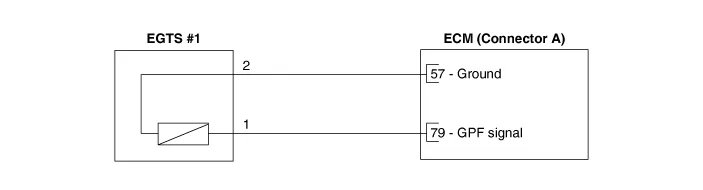
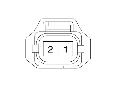
Harness Connector
EGTS #2
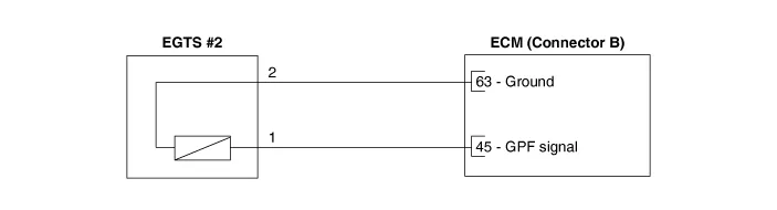
Harness Connector
EGTS #3
Repair procedures
| Inspection |
| 1. |
Turn ignition switch OFF. |
| 2. |
Disconnect the connector of exhaust gas temperature sensors #1/#2/#3. |
| 3. |
Measure resistance between sensor signal terminal and ground terminal. |
| 4. |
Check that the resistance is within the specification. Exhaust Gas Temperature Sensor [EGTS #1, #2, #3 (T3, T4, T5)]
|
| Removal & Installation |
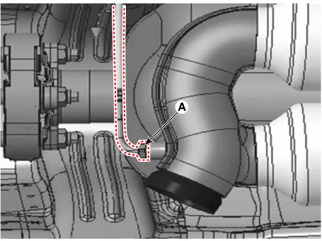
[EGTS #1]
| 1. |
Turn the ignition switch OFF and disconnect the battery negative (-) terminal. |
| 2. |
Remove the floor under cover. |
| 3. |
Disconnect the EGTS connector (A).
|
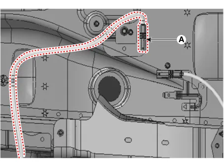
| 4. |
Remove the EGTS (A).
|
| 5. |
Install the sensor in the reverse order of removal.
|

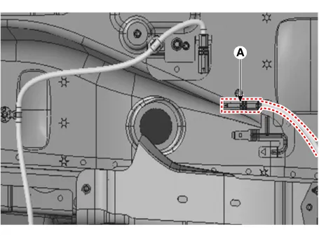
[EGTS #2]
| 1. |
Turn the ignition switch OFF and disconnect the battery negative (-) terminal. |
| 2. |
Remove the floor under cover. |
| 3. |
Disconnect the EGTS connector (A).
|
| 4. |
Remove the EGTS (A).
|
| 5. |
Install the sensor in the reverse order of removal.
|
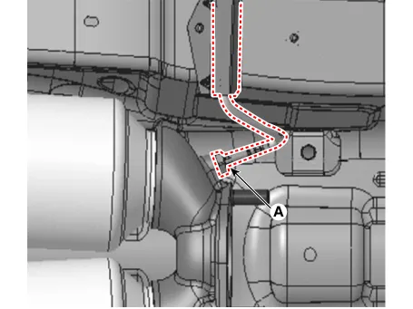
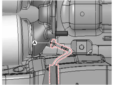
[EGTS #3]
| 1. |
Turn the ignition switch OFF and disconnect the battery negative (-) terminal. |
| 2. |
Remove the floor under cover. |
| 3. |
Disconnect the EGTS connector (A).
|

| 4. |
Remove the EGTS (A).
|
| 5. |
Install the sensor in the reverse order of removal.
|


Other information:
Kia Stinger (CK) 2018-2023 Service Manual: ECS Control Unit
Repair procedures Removal 1. Turn ignition switch OFF and disconnect the negative (-) battery cable. 2. Remove the luggage side trim. (Refer to Body - "Luggage side trim") 3. Disconnect the ECS control unit connector (A). 4. Loosen the ECS control unit bracket nut and then remove the ECS control unit (A).Kia Stinger (CK) 2018-2023 Service Manual: Vehicle recognition
Some vehicles ahead in your lane cannot be recognized by the sensor as follows: - Narrow vehicles such as motorcycles or bicycles - Vehicles offset to one side - Slow-moving vehicles or suddendecelerating vehicles - Stopped vehicles - Vehicles with small rear profiles such as trailers with no loads A vehicle ahead cannot be recognized correctly by the sensor if any of following occurs: - When the vehicle is pointing upwards due to overloading in the trunk or luggage area.Categories
- Manuals Home
- Kia Stinger Owners Manual
- Kia Stinger Service Manual
- New on site
- Most important about car
