Kia Stinger CK: Engine Control System / Heated Oxygen Sensor (HO2S)
Specifications
| Specification |
HO2S [Bank 1/Sensor 1]
|
Item |
Specification |
|
Heater Resistance (Ω) |
2.5 - 4.0 [20°C(68°F)] |
HO2S [Bank 1/Sensor 2]
|
Item |
Specification |
|
Heater Resistance (Ω) |
3.3 - 4.1 [20°C(69.8°F)] |
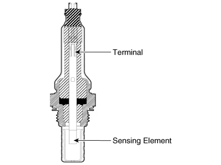
Description and operation
| Description |
Heated Oxygen Sensor (HO2S), consisting of zirconium and alumina, is installed on both upstream and downstream of the Catalytic Converter to detect the air/fuel ratio and send it to the ECM.
The sensor must be heated in order to operate properly. To keep it heated, the sensor has a heater which is controlled by the ECM via a duty cycle signal. When the exhaust gas temperature is lower than the specified value, the heater warms up the sensor tip.
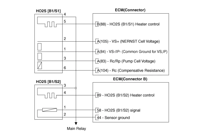
Schematic diagrams
| Circuit Diagram |
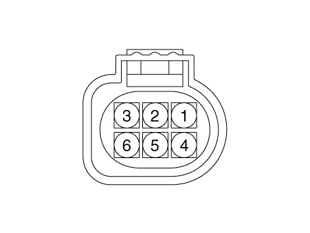
Harness Connector
[Bank 1 / Sensor 1]
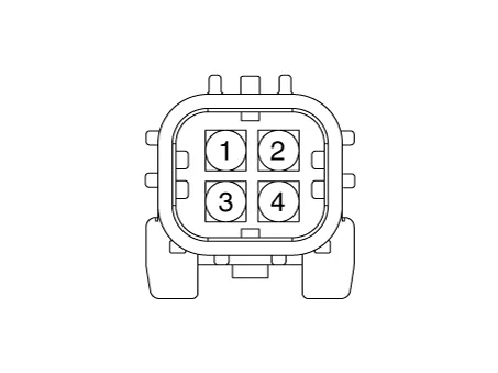
[Bank 1 / Sensor 2]
Repair procedures
| Inspection |
| 1. |
Switch "OFF" the ignition. |
| 2. |
Disconnect the HO2S connector. |
| 3. |
Measure resistance between the HO2S terminals 4 and 5 [B1/S1].
|
| 4. |
Measure resistance between the HO2S terminals 3 and 4 [B1/S2].
|
| 5. |
Check that the resistance is within the specification. |
| Removal |
Note that the SST (Part No. : 09392-1Y100 or 09392-2H100) is useful when removing the heated oxygen sensor. |

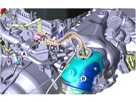
[Bank 1 / Sensor 1]
| 1. |
Switch "OFF" the ignition and disconnect the negative (-) battery terminal. |
| 2. |
Disconnect the connector (A), and then remove the sensor (B).
|
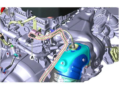
[Bank 1 / Sensor 2]
| 1. |
Switch "OFF" the ignition and disconnect the negative (-) battery terminal. |
| 2. |
Disconnect the connector (A).
|
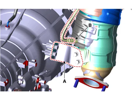
| 3. |
Lift the vehicle. |
| 4. |
Remove the catalytic converter bracket (A). |
| 5. |
Remove the sensor (B).
|
| Installation |
|
| 1. |
Install in the reverse order of removal.
|


Other information:
Kia Stinger (CK) 2018-2023 Service Manual: Emergency Call (eCall) Unit
Components and components location Component The eCall unit for AVN is equipped in AVN head unit. Repair procedures Removal Carry out the Test Mode after: – Replacing the eCall unit – Replacing the Back-up Battery (BUB) – Replacing the eCall speaker and MIC – Replacing the eCall antenna and roof antenna • Be careful not to scratch the cluster fascia panel and related parts.Kia Stinger (CK) 2018-2023 Service Manual: ETC (Electronic Throttle Control) System
Specifications Specification [Throttle Position Sensor (TPS)] Throttle Angle(°) Output Voltage(V) [Ref=5V] TPS1 TPS2 0 0.0 5.0 10 0.48 4.52 20 0.95 4.05 30 1.Categories
- Manuals Home
- Kia Stinger Owners Manual
- Kia Stinger Service Manual
- New on site
- Most important about car
