Kia Stinger CK: ISG (Idle Stop & Go) System / Brake switch
Components and components location
| Components |
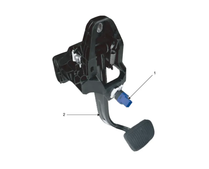
| 1. Brake switch |
2. Brake pedal |
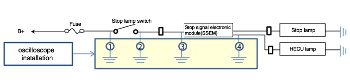
Schematic diagrams
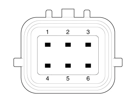
| Terminal function |

|
Pin No |
Description |
|
1 |
IGN1 |
|
2 |
IBU |
|
3 |
- |
|
4 |
B+ |
|
5 |
Stop lmap |
|
6 |
Ground |
Troubleshooting
| Troubleshooting |
| 1. |
Part diagnosis
|
| 2. |
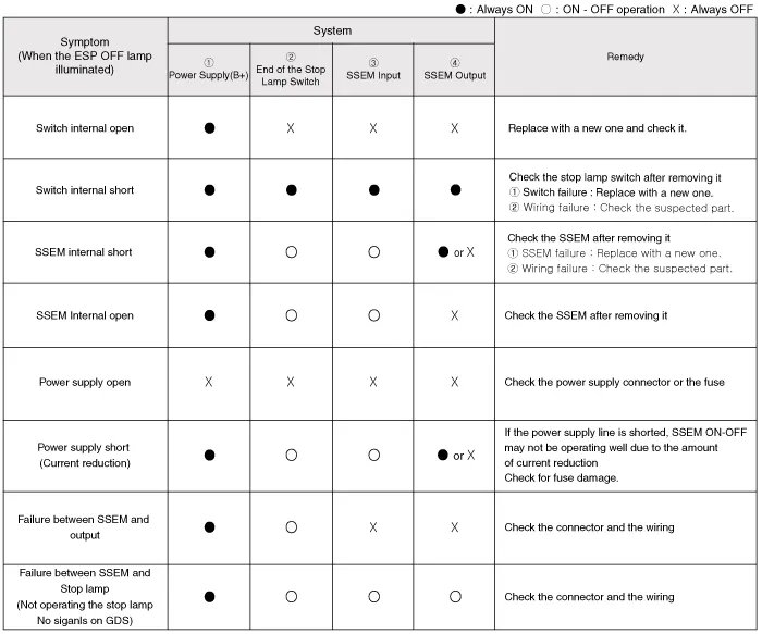
Symptom diagnosis
|
| 3. |
Stop lamp switch system diagnosis
SSEM : Stop Signal Electronic Module |
| 4. |
Refer to DTC guide when the related DTC codes are displayed. |
Repair procedures
| Removal |
| 1. |
Turn ignition switch OFF and disconnect the negative (-) battery cable. |
| 2. |
Remove the crash pad lower panel. (Refer to Body - "Crash Pad Lower Panel") |
| 3. |
Remove the knee airbag. (Refer to Restraint - "Knee airbag") |
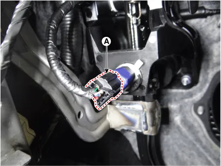
| 4. |
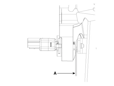
Disconnect the brake lamp switch connector (A).
|
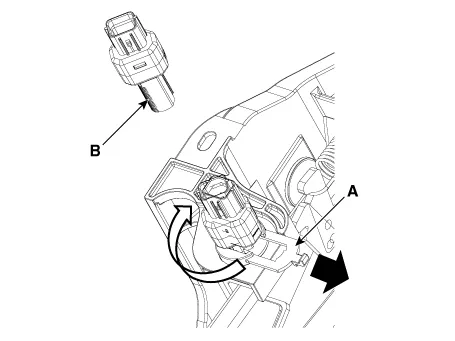
| 5. |
Pull the locking plate (A) as indicated by the arrow and then turn brake switch (B) 45° clockwise and remove it.
|
| 6. |
Inspect a removed stop lamp switch along the below procedures.
|
| Installation |
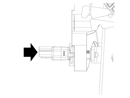
| 1. |
Fix the brake pedal arm and insert fully the brake switch so that the contact part is invisible.
|
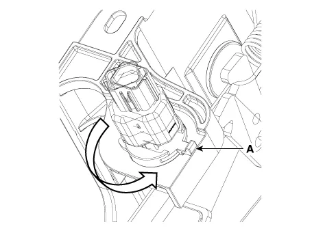
| 2. |
After inserting, turn the brake switch 45° counterclockwise, and then assemble locking plate by pushing.
|
| 3. |
Confirm the gap between stop lamp switch and bracket.
|

| 4. |
Install the stop lamp switch connector (A).
|


Other information:
Kia Stinger (CK) 2018-2023 Service Manual: Vehicle stability management (VSM)
This system provides further enhancements to vehicle stability and steering responses when a vehicle is driving on a slippery road or a vehicle detects changes in coefficient of friction between right wheels and left wheels when braking. WARNING - Tire/ Wheel size When replacing tires and wheels, make sure they are the same size as the original tires and wheels installed.Components and components location Component Location 1. Fuel filler door open switch 2. Fuel filler door release actuatorCategories
- Manuals Home
- Kia Stinger Owners Manual
- Kia Stinger Service Manual
- New on site
- Most important about car
