Kia Stinger CK: ISG (Idle Stop & Go) System / Door switch
Description and operation
| Description |
Via the seat belt/door switch, the ISG function can detect if the driver side seat belt is fastened and the driver side door is closed. If the driver side seat belt/door are not fastened/closed, the ISG system will not operate. If the seat belt/door are unfastened/opened, the engine will not start or stop by the ISG function for safety reasons.
Repair procedures
| Inspection |
Front Door Lock Module Inspection
| 1. |
Remove the front door trim. (Refer to Body - "Front Door Trim") |
| 2. |
Remove the front door module. (Refer to Body - "Front Door Module") |
| 3. |
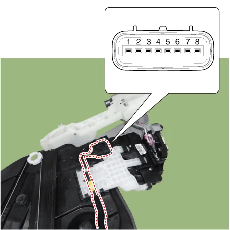
Disconnect the connector from the actuator.
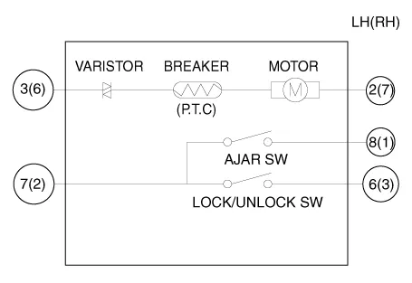
[Central Lock]
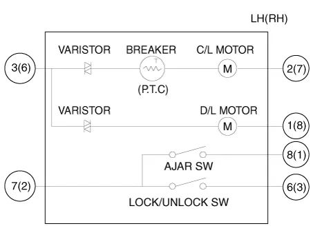
[Dead Lock]
|
||||||||||||||||||||||||||||||||||||||||||||||||||||||||||
| 4. |
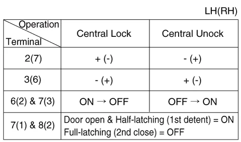
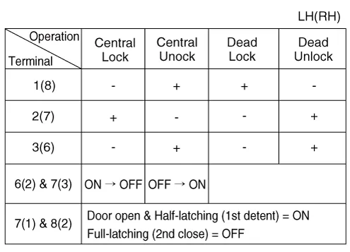
Check actuator operation by connecting power and ground as shown below. To prevent damage to the actuator, apply battery voltage only momentarily. [Central Lock (Without key switch)]
[Dead Lock (Without Key Switch)]
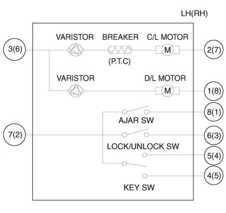
[Dead Lock (With Key Switch)]
[Central Lock]
[Dead Lock]
|
| Installation |
| 1. |
Install in the reverse order of removal. |


Other information:
Description and operation Description The ISG OFF switch on the floor console can be used to deactivate the ISG function. Repair procedures Removal Put on gloves to protect your hands. • When prying with a flat-tip screwdriver or use a prying trim tool, wrap it with protective tape, and apply protective tape around the related parts, to prevent damage.If emergency towing is necessary, we recommend having it done by an authorized Kia dealer or a commercial tow-truck service. Proper lifting and towing procedures are necessary to prevent damage to the vehicle. The use of wheel dollies(1) or flatbed is recommended. On AWD vehicles, your vehicle must be towed with a wheel lift and dollies or flatbed equipment with all the wheels off the ground.Categories
- Manuals Home
- Kia Stinger Owners Manual
- Kia Stinger Service Manual
- New on site
- Most important about car
