Kia Stinger CK: Engine Electrical System / Cruise Control System
Contents:
Description and operation
| Cruise Control |
The cruise control system is engaged by the cruise "ON/OFF" main switch located on the right-hand side of steering wheel column. The system has the capability to cruise, coast, accelerate and resume speed.
It also has a safety interrupt, engaged upon depressing brake or shifting select lever.
The ECM is the control module for this system. The main components of cruise control system are mode control switches, transmission range switch, brake switch, vehicle speed sensor, ECM and ETS motor that connect throttle body.
The ECM has a low speed limit that prevents system engagement below a minimum speed of 40km/h (25mph).
The operation of the controller is controlled by mode control switches located on steering wheel.
Transmission range switch and brake switch are provided to disengage the cruise control system. The switches are on brake pedal bracket and transmission. When the brake pedal is depressed or select lever shifted, the cruise control system is electrically disengaged and the throttle is returned to the idle position.
Cruise main switch (ON/OFF)
The cruise control system is engaged by pressing the cruise "ON/OFF" main switch. Pressing the cruise "ON/OFF" main switch again releases throttle, clears cruise memory speed, and puts vehicle in a non-cruise mode.
Set/Coast switch (SET/–)
The "SET/–" switch located on right-hand side of steering wheel column, has two functions.
The set function - Push the "SET/–" switch and release it at the desired speed. The SET indicator light in the instrument cluster will illuminate. Release the accelerator pedal. The desired speed will automatically be maintained.
The coast function - Push the "SET/–" switch and hold it when the cruise control is on. The vehicle will gradually slow down. Release the switch at the desired speed. The desired speed will be maintained.
Push the "SET/–" switch and release it quickly. The cruising speed will decrease by 2.0km/h (1.2mph).
Resume/Accel switch (RES/+)
The "RES/+" switch located on right-hand side of steering wheel column, has two functions.
The resume function - If any method other than the cruise “ON/OFF” main switch was used to cancel cruising speed temporarily and the system is still activated, the most recent set speed will automatically resume when the "RES/+" switch is pushed. It will not resume, however, if the vehicle speed has dropped below approximately 40km/h (25mph).
The accel function - Push the "RES/+" switch and hold it when the cruise control is on. The vehicle will gradually accelerate. Release the switch at the desired speed. The desired speed will be maintained.
Push the "RES/+" switch and release it quickly. The cruising speed will increase by 2.0km/h (1.2mph).
Cancel switch (CANCEL)
The cruise control system is temporarily disengaged by pushing the "CANCEL" switch.
Cruise speed canceled by this switch can be recovered by pushing the "RES/+" switch.
Schematic diagrams
| System Block Diagram |

Component Parts And Function Outline
|
Component part |
Function |
|
|
Vehicle-speed sensor, ESP/ABS Control Module |
Converts vehicle speed to pulse. |
|
|
ECM |
Receives signals from sensor and control switches. |
|
|
Cruise control indicator |
Illuminate when CRUISE main switch is ON (Built into cluster) |
|
|
Cruise Control switches |
CRUISE switch |
Switch for automatic speed control power supply. |
|
RES+ switch |
Controls automatic speed control functions by Resume/Accel switch (Set/Coast
switch) |
|
|
SET- switch |
||
|
Cancel switches |
Cancel switch |
Sends cancel signals to ECM. |
|
Brake-pedal switch |
||
|
Transaxle range switch (A/T) |
||
|
ETC motor |
Regulates the throttle valve to the set opening by ECM. |
|
* ETC Motor : Electronic Throttle Control Motor
Troubleshooting
| Trouble Symptom Charts |
| Trouble Symptom 1 |
Trouble Symptom 2
|
Trouble symptom |
Probable cause |
Remedy |
|
The set vehicle speed varies greatly upward or downward "Surging" (repeated alternating acceleration and deceleration) occurs after setting |
Malfunction of the vehicle speed sensor circuit |
Repair the vehicle speed sensor system, or replace the part |
|
Malfunction of ECM |
Check input and output signals at ECM |
Trouble Symptom 3
|
Trouble symptom |
Probable cause |
Remedy |
|
The CC system is not canceled when the brake pedal is depressed |
Damaged or disconnected wiring of the brake pedal switch |
Repair the harness or replace the brake pedal switch |
|
Malfunction of the ECM signals |
Check input and output signals at ECM |
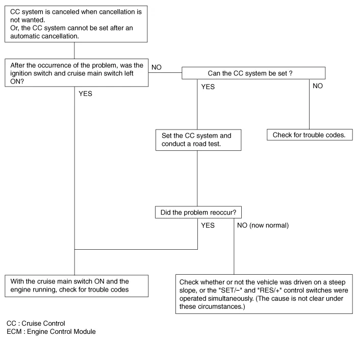
Trouble Symptom 4
|
Trouble symptom |
Probable cause |
Remedy |
|
The CC system is not canceled when the shift lever is moved to the "N" position
(It is canceled, however, when the brake pedal is depressed) |
Damaged or disconnected wiring of inhibitor switch input circuit |
Repair the harness or repair or replace the inhibitor switch |
|
Improper adjustment of inhibitor switch |
||
|
Malfunction of the ECM signals |
Check input and output signals at ECM |
Trouble Symptom 5
|
Trouble symptom |
Probable cause |
Remedy |
|
Cannot decelerate (coast) by using the "SET/–" switch |
Temporary damaged or disconnected wiring of "SET/–" switch input circuit
|
Repair the harness or replace the "SET/–" switch |
|
Malfunction of the ECM signals |
Check input and output signals at ECM |
Trouble Symptom 6
|
Trouble symptom |
Probable cause |
Remedy |
|
Cannot accelerate or resume speed by using the "RES/+" switch |
Damaged or disconnected wiring, or short circuit, or "RES/+" switch input
circuit |
Repair the harness or replace the "RES/+" switch |
|
Malfunction of the ECM signals |
Check input and output signals at ECM |
Trouble Symptom 7
|
Trouble symptom |
Probable cause |
Remedy |
|
CC system can be set while driving at a vehicle speed of less than 40km/h
(25mph), or there is no automatic cancellation at that speed |
Malfunction of the vehicle-speed sensor circuit |
Repair the vehicle speed sensor system, or replace the part |
|
Malfunction of the ECM signals |
Check input and output signals at ECM |
Trouble Symptom 8
|
Trouble symptom |
Probable cause |
Remedy |
|
The cruise main switch indicator lamp does not illuminate (although CC system
is normal) |
Damaged or disconnected bulb of cruise main switch indicator lamp |
Repair the harness or replace the part. |
|
Harness damaged or disconnected |
Cruise Control Switch
Components and components location
| Components |
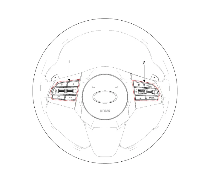
| 1. Left Remote Control Switch
(Audio + Bluetooth + Voice) |
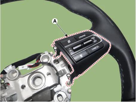
2. Right Remote Control Switch
(Trip Computer + ACC + SCC) |
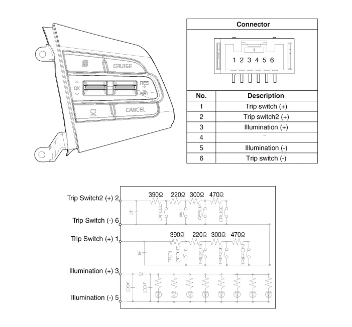
Schematic diagrams
| Circuit Diagram |
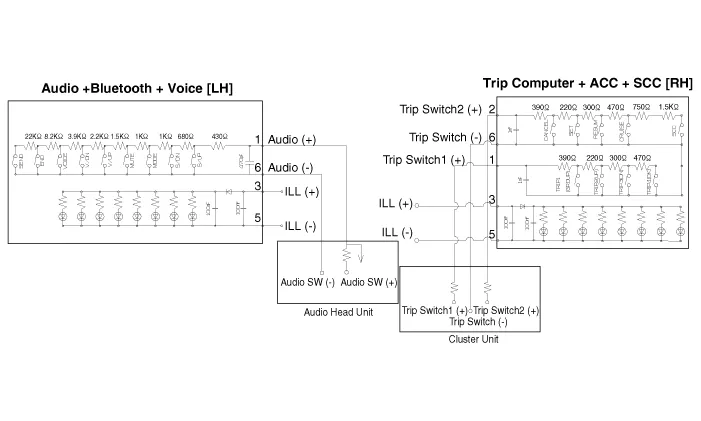
| [Audio + Bluetooth + Voice] |
| [Trip + ACC] |

| [Trip + ACC + SCC] |
Repair procedures
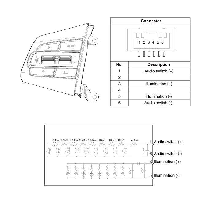
| Inspection |
| 1. |
Check for resistance between terminals in each switch position (RH).
[RH : Trip + SCC + ACC]
|
| Removal |
| 1. |
Disconnect the negative (-) battery terminal. |
| 2. |
Remove the steering wheel assembly. (Refer to Steering System - "Steering Wheel") |
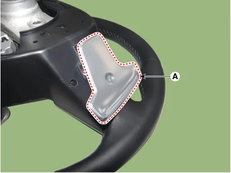
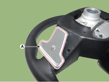
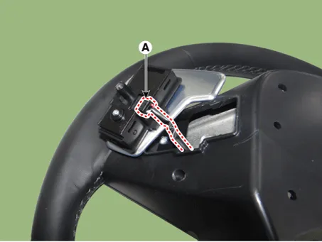
| 3. |
Remove the paddle shift switch (A) after loosening the mounting screws. [LH]
[RH]
|


| 4. |
Disconnect the paddle shift switch connector (A). [LH]
[RH]
|

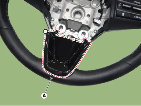
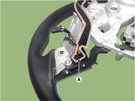
| 5. |
Remove the steering front cover (A) after loosening the mounting screws.
|
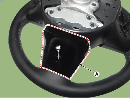
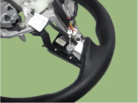
| 6. |
Remove the steering rear cover (A) after loosening the mounting screws.
|
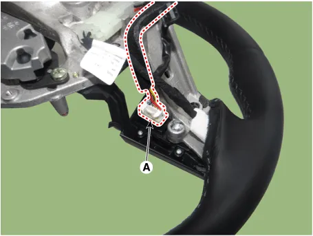
| 7. |
Remove the steering back cover (A) after loosening the mounting screws.
|

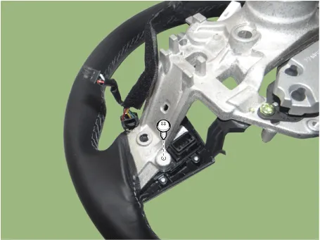
| 8. |
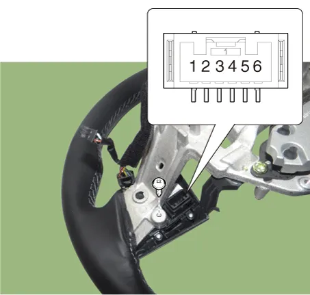
Disconnect the steering wheel remote control connector (A). [LH]
[RH]
|
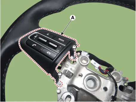
| 9. |
Remove the steering wheel remote control (A) after loosening the mounting screws. [LH]
[RH]
|
| Installation |
| 1. |
Install the steering wheel remote control. |
| 2. |
Connect the steering remote control connector. |
| 3. |
Install the steering back cover. |
| 4. |
Install the steering rear cover. |
| 5. |
Install the steering front cover. |
| 6. |
Connect the paddle shift switch connector. |
| 7. |
Install the paddle shift switch. |
| 8. |
Install the steering wheel assembly. |
| 9. |
Connect the negative (-) battery terminal. |


Other information:
Kia Stinger (CK) 2018-2023 Service Manual: Fuse/relay panel description
■ Driver’s side fuse panel ■ Engine compartment fuse panel ■ Rear fuse box panel ■ Battery box fuse panel Inside the fuse/relay panel covers, you can find the fuse/relay label describing fuse/relay name and capacity. ✽ NOTICE Not all fuse panel descriptions in this manual may be applicable to your vehicle. It is accurate at the time of printing.Driver`s seat (1) Driver position memory system* (2) Forward and backward (3) Seatback angle (4) Seat cushion height (5) Lumbar support (6) Cushion extension (7) Seat back bolster control (8) Headrest Front Passenger`s seat (9) Forward and backward (10) Seatback angle (11) Seat cushion height (12) Lumbar support (13) Headrest Rear seat (14) Armrest (15) Headrest (16) Seatback folding lever WARNING - Loose objects Do not place anything in the driver's foot well or under the front seats.Categories
- Manuals Home
- Kia Stinger Owners Manual
- Kia Stinger Service Manual
- New on site
- Most important about car
Contents
