Kia Stinger CK: Windshield Wiper/Washer / Head Up Display (HUD) System
Contents:
Components and components location
| Components Location |
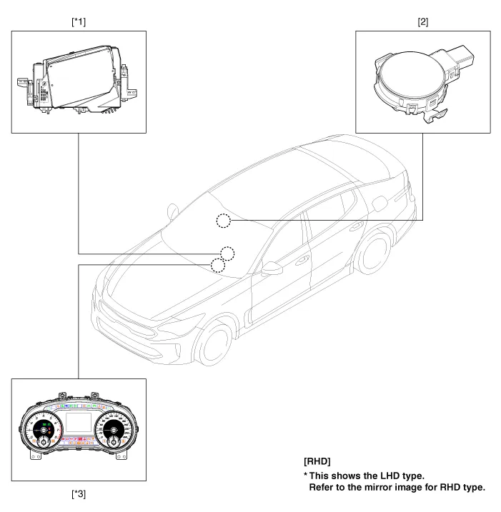
| 1. Head Up Display (HUD) 2. Ambient light sensor |
3. Cluster (User setting menu
ON/OFF, Display brightness) |
Description and operation
| Description |
| 1. |
System operation
HUD system displays various information on the windshield glass which minimizes the driver’s eye movement to enhance safety and convenience. The Head Up Display reflects the TFT LCD images to two mirrors (flat/concave) and displays them 2.2m ahead from the driver's eye. Information provided by HUD ;
|

| 2. |
HUD Display Contents
|

| 3. |
HUD Unit Head Up Display : Output various vehicle system information on windshield glass via CAN
|
| 4. |
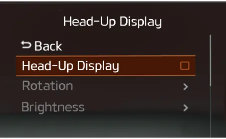
Cluster : Select display function in content setting in [Head Up Display] menu. [ON/OFF Setting]
[Display brightness]
|

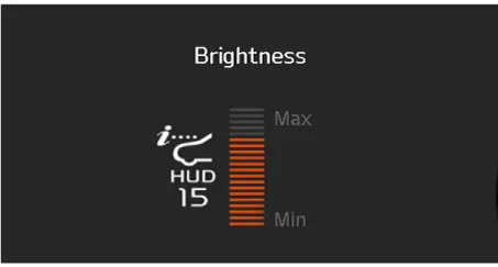
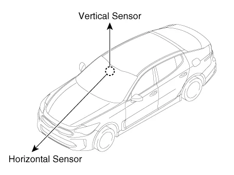
| 5. |
Illumination Sensor : It is equipped with bidirectional (vertical and horizontal) sensor. HUD brightness is controlled depending on horizontal measurement (ambient brightness).
|
| 6. |
Windshield glass : Windshield glass exclusive for Head Up Display is built in with double image removal film.
|

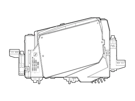
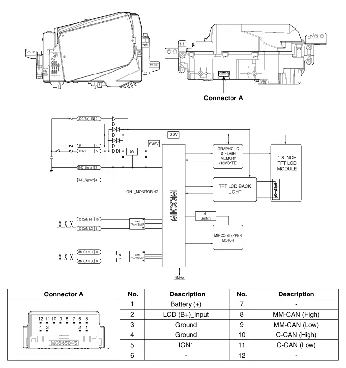
Head Up Display (HUD) Unit
Components and components location
| Component |
Repair procedures
| Removal |
Put on gloves to prevent hand injuries. |
|
| 1. |
Disconnect the negative (-) battery terminal. |
| 2. |
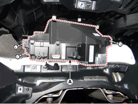
Remove the head up display bezel (A) by using a remover.
|

| 3. |
Remove the instrument cluster. (Refer to Indicators And Gauges - "Instrument Cluster") |
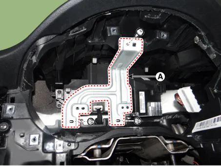
| 4. |
Remove the head up display unit bracket (A) after loosening the mounting screw and nuts.
|
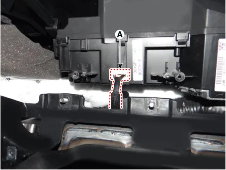
| 5. |
Disconnect the head up display unit connector (A).
|
| 6. |
Remove the head up display unit (A) after loosening the mounting screws.
|
| Installation |
| 1. |
Connect the connector after installing the head up display unit. |
| 2. |
Install the head up display unit bracket. |
| 3. |
Install the instrument cluster. |
| 4. |
Install the head up display bezel. |
| 5. |
Connect the negative (-) battery terminal. |
| Inspection |
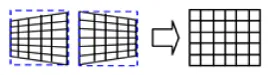
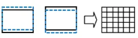
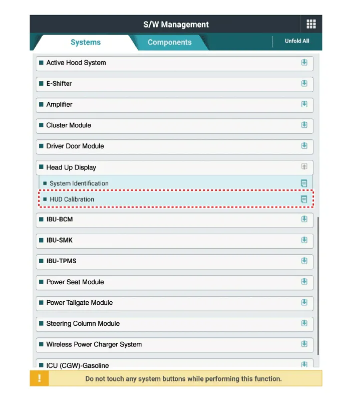
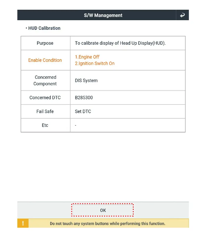
If a part of the head up display footage is distorted or it is not at eye level with the driver a Global Diagnostic System (KDS) can be used to carry out calibration.
| 1. |
Calibration is required:
|
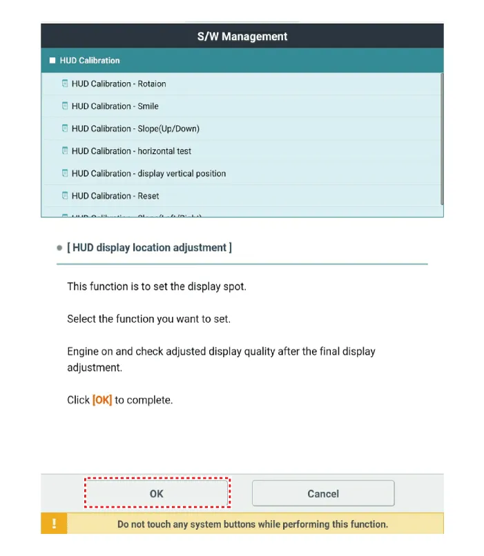
| 2. |
Calibration items
|


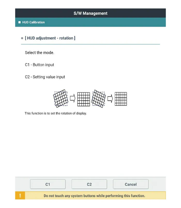
| 3. |
Process of calibration
|

Troubleshooting
| Troubleshooting |
|
Category |
Error symptoms |
Inspection item |
Detailed inspection item |
Related parts |
||||||||||||||
|
Lighting |
|
|
|
Light sensor CGW Cluster |
||||||||||||||
|
Adjustment function |
|
|
|
HUD Cluster |


Other information:
Kia Stinger (CK) 2018-2023 Service Manual: Starting System
Description and operation Description The starting system includes the battery, starter, solenoid switch, ignition switch, inhibitor switch (A/T), clutch pedal switch (M/T), ignition lock switch, connection wires and the battery cable. When the ignition key is turned to the start position, current flows and energizes the starter motor's solenoid coil.Kia Stinger (CK) 2018-2023 Service Manual: Pantoscopic Camera
Components and components location Components Front View Camera Side View Camera Rear View Camera Repair procedures Removal In case of bad quality or poor focus, be sure to check the camera lense surface condition and foreign materials.Categories
- Manuals Home
- Kia Stinger Owners Manual
- Kia Stinger Service Manual
- New on site
- Most important about car
Contents
