
Kia Stinger CK: Airbag Module / Curtain Airbag (CAB) Module
Description and operation
| Description |
Installed inside the headliner, the curtain airbags (CAB) protect the driver and passengers from danger in the eThe SRSCM determines deployment of curtain airbag based on side impact sensor (SIS) signal.The SRSCM determines deployment of curtain airbag by using side impact sensor (SIS) signal.
Never attempt to measure the circuit resistance of the airbag module even if you are using the specified tester. If the circuit resistance is measured with a tester, accidental airbag deployment will result in serious personal injury. |

Components and components location
| Components |
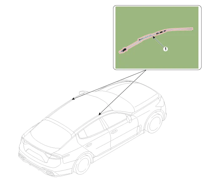
| 1. Curtain Airbag (CAB) |
Repair procedures
| Removal |
| 1. |
Disconnect the battery negative terminal, and wait for at least three minutes before beginning to work. |
| 2. |
Remove the roof trim. (Refer to Body (Interior and Exterior) - "Roof Trim Assembly") |
| 3. |
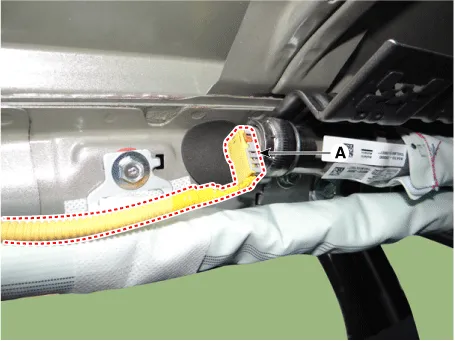
Disconnect the connector (A) from the curtain airbag module.
|
| 4. |
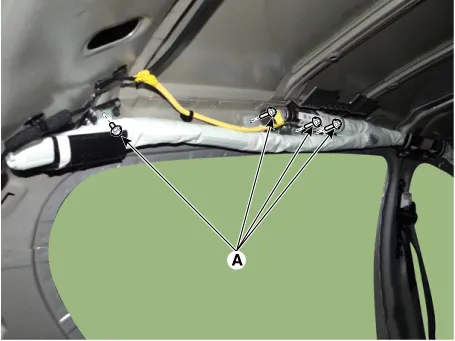
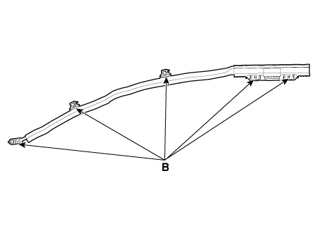
Loosen the curtain airbag bolts and nuts and then remove the curtain airbag.
|
| Installation |
| 1. |
Disconnect the battery negative terminal, and wait for at least three minutes before beginning to work. |
| 2. |
Install in the reverse order of removal. |
| 3. |
Reconnect the negative battery terminal. |
| 4. |
After installing the curtain airbag (CAB), confirm proper system operation: Switch "ON" the ignition. The SRS indicator light should turn on for about six seconds and then off. |


Other information:
Kia Stinger (CK) 2018-2023 Service Manual: Steering Gear box
Components and components location Components 1. Tie rod end 2. R-MDPS motor Repair procedures Removal 1. Remove wheel nuts, front wheel and tire (A) from hub. Tightening torque : 107.9 - 127.5 N·m (11.0 - 13.0 kgf·m, 79.6 - 94.0 lb·ft) Be careful not to damage the wheel bolts when removing the wheel and tire (A).Kia Stinger (CK) 2018-2023 Service Manual: Heated Oxygen Sensor (HO2S)
Specifications Specification HO2S [Bank 1/Sensor 1] Item Specification Heater Resistance (Ω) 2.5 - 4.0 [20°C(68°F)] HO2S [Bank 1/Sensor 2] Item Specification Heater Resistance (Ω) 3.3 - 4.1 [20°C(69.8°F)] Description and operation Description Heated Oxygen Sensor (HO2S), consisting of zirconium and alumina, is installed on both upstream and downstream of the Catalytic Converter to detect the air/fuel ratio and send it to the ECM.Categories
- Manuals Home
- Kia Stinger Owners Manual
- Kia Stinger Service Manual
- New on site
- Most important about car
