Kia Stinger CK: Engine Control System / CVVT Oil Control Valve (OCV) [Bank1/Exhaust]
Specifications
Item
|
Specification
|
Coil Resistance (Ω)
|
6.9 - 7.9 [20°C(68°F)]
|
Description and operation
Continuous Variable Valve Timing (CVVT) system advances or retards the valve
timing of the exhaust valve in accordance with the ECM control signal which is calculated
by the engine speed and load.
By controlling CVVT, the valve over-lap or under-lap occurs, which in turn improves
fuel efficiency, reduces exhaust gases (NOx, HC) and improves engine performance
by reducing pumping loss, generating internal EGR effect, improving combustion stability,
improving volumetric efficiency and increasing expansion work.
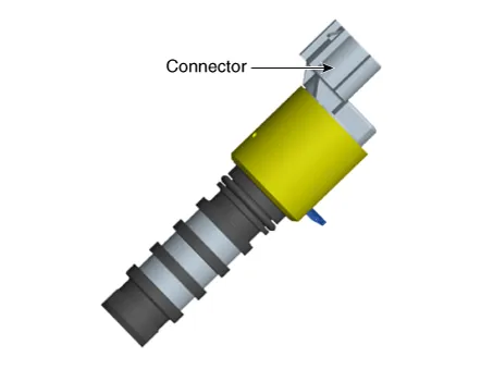
This system consists of
-the CVVT Oil Control Valve (OCV) which supplies the engine oil to the cam phaser
or cuts the engine oil from the cam phaser in accordance with the ECM PWM (Pulse
With Modulation) control signal,
-and the Cam Phaser which varies the cam phase by using the hydraulic force of
the engine oil.
The engine oil released from the CVVT oil control valve varies the cam phase
in the direction (Intake Advance/Exhaust Retard) or opposite direction (Intake Retard/Exhaust
Advance) of the engine rotation by rotating the rotor connected with the camshaft
inside the cam phaser.
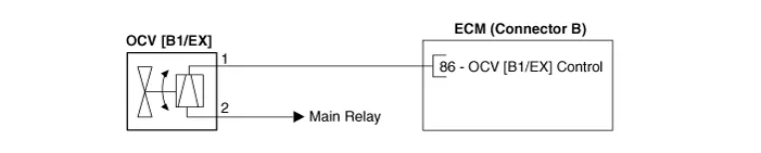
Schematic diagrams
Harness Connector
Repair procedures
| 1. |
Switch "OFF" the ignition.
|
| 2. |
Disconnect the OCV connector.
|
| 3. |
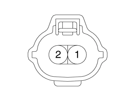
Measure resistance between the OCV terminals 1 and 2.
|
| 4. |
Check that the resistance is within the specification.
|
Specification: 6.9 - 7.9 Ω [20°C(68°F)]
|
|
| 1. |
Remove the oil control valve.
(Refer to CVVT Oil Control Valve - "Removal")
|
| 2. |
Check that the valve operates properly when battery voltage is applied
to terminals 1 and 2 of the valve connector.
|
| 1. |
Switch "OFF" the ignition and disconnect the negative (-) battery terminal.
|
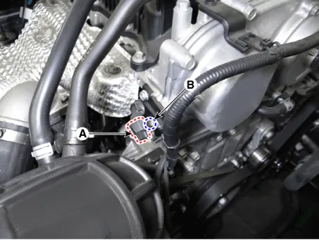
| 2. |
Disconnect the CVVT oil control valve connector (A).
|
| 3. |
Remove the installation bolt (B), and then remove the valve from the
engine.
|
CVVT oil control valve mounting bolt:
9.8 - 11.8 N·m (1.0 - 1.2 kgf·m, 7.2 - 8.7 lb·ft)
|
[Bank 1 / Exhaust]
|
| • |
Install the component to the specified torques.
|
| • |
Note that internal damage may occur when the component is dropped.
If the component has been dropped, inspect before installing.
|
| • |
Apply engine oil to the valve O-ring.
|
|
| 1. |
Install in the reverse order of removal.
|
CVVT oil control valve mounting bolt:
9.8 - 11.8 N·m (1.0 - 1.2 kgf·m, 7.2 - 8.7 lb·ft)
|
|


