
Kia Stinger CK: Windshield Wiper/Washer / Emergency Call System
Contents:
Components and components location
| Components |
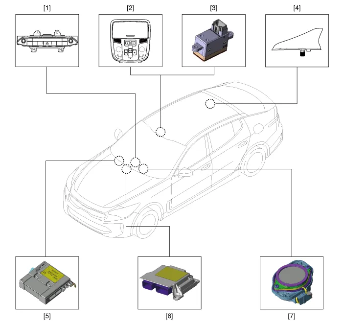
| 1. Head unit (AVN, Audio) 2. Emergency call button 3. Emergency call MIC 4. Roof antenna 5. Emergency call unit |
6. Supplemental restraint system
control module (SRSCM) 7. Emergency call speaker |
Description and operation
| Description |
Emergency Call (eCall)
When an accident occurs or the user's request is detected, it notifies the call center of the vehicle status using the wireless network so that the center can provide necessary emergency service.
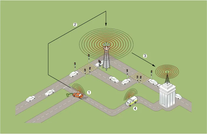
| 1. Emergency Call 2. Radio Communication network |
3. Public-Safety Answering Point
(PSAP) 4. Emergency rescue service |
eCall Function
| 1. |
Automatic notification: Airbag signal triggered by accident is detected and the call center is automatically notified of the accident.
|

| 2. |
Manual notification: The driver can operate the SOS button to notify the call center of the accident manually.
|
Configuration of eCall Controller

Input buttons & Indicators
SOS button : Press this button to make a call to the call center.
SOS TEST button : Press this button for 10 seconds or more to enter the test mode and reset the eCall system.
LED indicator lamp : The red and green LEDs turn on for 3 seconds after the ACC is on and stay turned off in standby until the key is turned off.
The red LED turns on when there is a problem with the eCall system.
The green LED turns on when the eCall system is operating normally.
Emergency Call (eCall) Unit ➤
Emergency Call (eCall) Button ➤


Other information:
❈ The actual air bags in the vehicle may differ from the illustration. Your vehicle is equipped with a side air bag in each front seat. The purpose of the air bag is to provide the vehicle's driver and/or the front passenger with additional protection than that offered by the seat belt alone. The side air bags are designed to deploy during certain side-impact collisions, depending on the crash severity, angle, speed and point of impact.Components and components location Components (1) [General Type] 1. Roof trim 2. Sunvisor 3. Assist handle bracket Components (2) [Panorama Sunroof Type] 1. Roof trim 2. Sunvisor 3. Assist handle bracketCategories
- Manuals Home
- Kia Stinger Owners Manual
- Kia Stinger Service Manual
- New on site
- Most important about car
Contents
