Kia Stinger CK: Controller / Heater Control Unit
Description and operation
| Description |
Smart Ventilation
It is a system that actively ventilates when the humidity inside the passenger compartment increases with the air conditioning OFF.
| 1. |
Entry condition
|
| 2. |
Release condition
|
| 3. |
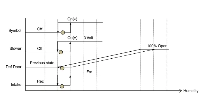
Operation Specifications When the humidity in the passenger compartment increases, the system below will be activated in the following order.
|

Components and components location
| Components |
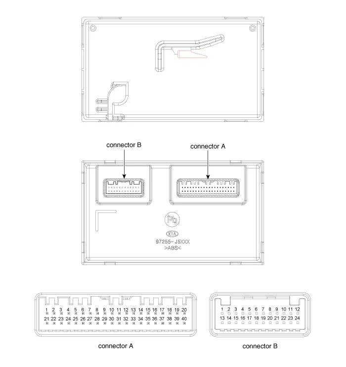
| Connector Pin Function |
[Connector A]
|
Pin NO |
Function |
Pin NO |
Function |
|
1 |
Mode Control Actuator (F/B) |
21 |
Mode Control Actuator (VENT) |
|
2 |
Intake Actuator (F/B) |
22 |
Mode Control Actuator (DEF) |
|
3 |
Passenger Side Temperature Control Actuator (F/B) |
23 |
Intake Actuator (FRE) |
|
4 |
Driver Side Temperature Control Actuator (F/B) |
24 |
Intake Actuator (REC) |
|
5 |
Auto Defogging Actuator (F/B) |
25 |
Passenger Side Temperature Control Actuator (COOL) |
|
6 |
- |
26 |
Passenger Side Temperature Control Actuator (WARM) |
|
7 |
Incar sensor (+) |
27 |
Driver side Temperature Control Actuator (COOL) |
|
8 |
Left Photo Sensor (-) |
28 |
Driver side Temperature Control Actuator (WARM) |
|
9 |
Right Photo Sensor (-) |
29 |
Auto Defogging Actuator (OPEN) |
|
10 |
Console Temperature Control Actuator (F/B) |
30 |
Auto Defogging Actuator (CLOSE) |
|
11 |
Console ON/OFF Actuator (F/B) |
31 |
- |
|
12 |
Console Switch (F/B) |
32 |
- |
|
13 |
Auto Defogging signal |
33 |
- |
|
14 |
Ambient Temperature Sensor (+) |
34 |
P CAN LOW |
|
15 |
Evaporator Temperature Sensor (+) |
35 |
P CAN HIGH |
|
16 |
- |
36 |
- |
|
17 |
Console Temperature Control Actuator (COOL) |
37 |
- |
|
18 |
Console Temperature Control Actuator (WARM) |
38 |
- |
|
19 |
Console ON/OFF Actuator (OPEN) |
39 |
- |
|
20 |
Console ON/OFF Actuator (CLOSE) |
40 |
Ground |
[Connector B]
|
Pin NO |
Function |
Pin NO |
Function |
|
1 |
Ground |
13 |
Ground |
|
2 |
Sensor Ground |
14 |
ECV (-) |
|
3 |
FET (GATE) |
15 |
ECV (+) |
|
4 |
FET Drain (F/B) |
16 |
- |
|
5 |
Blower Motor (+) |
17 |
- |
|
6 |
- |
18 |
PTC ON Signal |
|
7 |
- |
19 |
PTC Relay 2 |
|
8 |
- |
20 |
PTC Relay 3 |
|
9 |
Sensor REF (5V) |
21 |
- |
|
10 |
- |
22 |
LIN BUS |
|
11 |
- |
23 |
IGN1 |
|
12 |
Battery (+) |
24 |
IGN2 |
Repair procedures
| Replacement |
| 1. |
Disconnect the negative (-) battery terminal. |
| 2. |
Remove the glove box hoursing. (Refer to Body - "Glove Box Hoursing") |
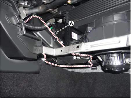
| 3. |
Remove the shower duct (A) after loosening the screw.
|
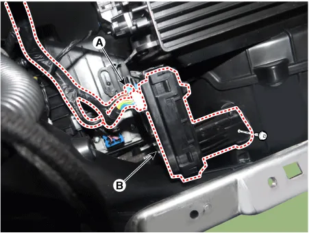
| 4. |
Disconnect the heater control unit connectors (A). |
| 5. |
Remove the heater control unit (B) after loosening the screws.
|
| 6. |
Install in the reverse order of removal. |


Other information:
Kia Stinger (CK) 2018-2023 Service Manual: Power Seat Motor
Components and components location Component Location 1. Slide motor 2. Reclining motor 3. Lumber support motor 4. Front height motor 5. Cushion extension motor 6. Rear height motor Description and operation Description Power seat motor is driven by a motor in the following.Kia Stinger (CK) 2018-2023 Service Manual: Rear Seat Belt Buckle
Components and components location Component Location 1. Rear seat belt buckle [RH] 2. Rear seat belt buckle [LH] Repair procedures Replacement Put on gloves to protect your hands. • Use a plastic panel removal tool to remove interior trim pieces without marring the surface.Categories
- Manuals Home
- Kia Stinger Owners Manual
- Kia Stinger Service Manual
- New on site
- Most important about car
