Kia Stinger CK: Crash Pad / Glove Box Housing
Components and components location
| Component Location |
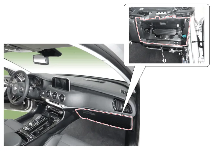
| 1. Glove box housing |
Repair procedures
| Replacement |
Put on gloves to protect your hands. |

|

| 1. |
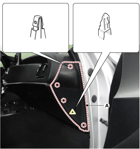
Remove the crash pad side cover [RH] (A) by using a remover.
|
| 2. |
Remove the crash pad garnish [RH] (A) after loosening the mounting screws.
|
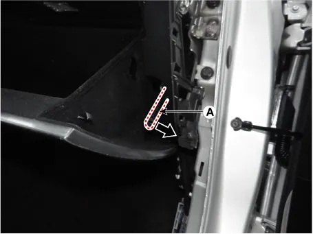
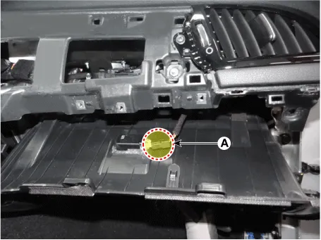
| 3. |
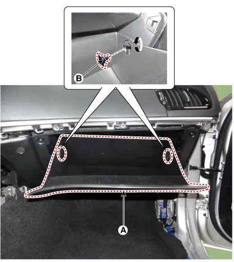
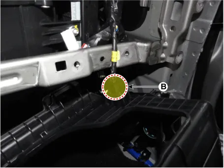
Pull out the both sides stopper (B) from the glove box (A).
|
| 4. |
Remove the air damper (A) from the glove box (B).
|
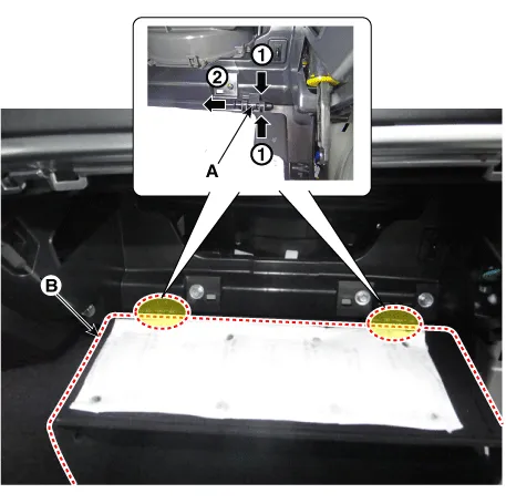
| 5. |
Remove the lock pins (A) and then remove the glove box (B).
|
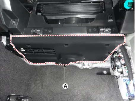
| 6. |
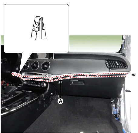
Separate the crash pad under cover [RH] (A).
|
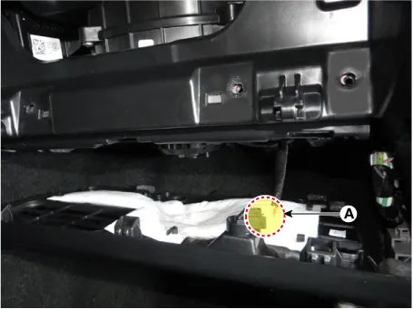
| 7. |
Disconnect the lamp connector (A) and remove crash pad under cover.
|
| 8. |
Separate the glove box housing (A) after loosening the mounting screws, bolts, and nuts.
|
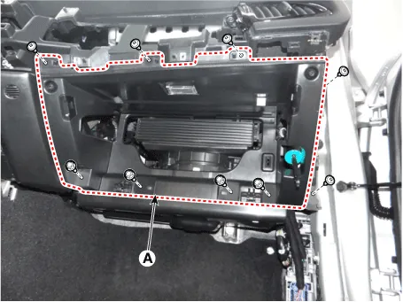
| 9. |
Remove the glove box housing after disconnecting the connector (A), (B).
|
| 10. |
Install in the reverse order of removal.
|


Other information:
Kia Stinger (CK) 2018-2023 Service Manual: Parking distance warningreverse precautions
The parking distance warningreverse may not sound consistently depending on the speed and shapes of the objects detected. The parking distance warningreverse may malfunction if the vehicle bumper height or sensor installation has been modified or damaged. Any non-factory installed equipment or accessories may also interfere with the sensor performance.Kia Stinger (CK) 2018-2023 Service Manual: Air bag non-inflation conditions
• In certain low-speed collisions the air bags may not deploy. The air bags are designed not to deploy in such cases because they may not provide benefits beyond the protection of the seat belts in such collisions. • Air bags are not designed to inflate in rear collisions, because occupants are moved backward by the force of the impact.Categories
- Manuals Home
- Kia Stinger Owners Manual
- Kia Stinger Service Manual
- New on site
- Most important about car
