Kia Stinger CK: Body (Interior and Exterior) / Crash Pad
Contents:
- Cluster Fascia Panel
- Center Fascia Panel
- Crash Pad Lower Panel
- Steering Column Shroud Panel
- Glove Box Housing
- Crash Pad Center Panel
- Main Crash Pad Assembly
- Cowl Cross Bar Assembly
Components and components location
| Components |
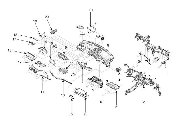
| 1. Cowl cross member bar 2. Main wiring 3. Main crash pad 4. Side air vent duct [RH] 5. Crash pad under cover [RH] 6. Crash pad lower panel [RH] 7. Crash pad center lower cover 8. Glove box housing 9. Fuse A/S cover 10. Crash pad garnish [RH] 11. Crash pad passenger side panel |
12. Steering column lower shroud
13. Cluster fascia upper panel 14. Cluster assembly 15. A.V.N monitor 16. monitor fascia panel 17. Crash pad side switch 18. Crash pad garnish [LH] 19. Crash pad driver side panel 20. Side air vent duct [LH] 21. Center speaker grille |
Cluster Fascia Panel ➤
Center Fascia Panel ➤
Crash Pad Lower Panel ➤
Steering Column Shroud Panel ➤
Glove Box Housing ➤
Crash Pad Center Panel ➤
Main Crash Pad Assembly ➤
Cowl Cross Bar Assembly ➤


Other information:
Kia Stinger (CK) 2018-2023 Service Manual: Auto Lighting Control System
Specifications Specifications Items Specifications Rated voltage 5V Load Max. 1mA (Relay load) Illuminations (LUX) 50 0.98 ± 0.2 V 150 1.74 ± 0.38 V Components and components location Component Location 1.Components and components location Component Location 1. Rear door latch Repair procedures Replacement Put on gloves to protect your hands. • Use a plastic panel removal tool to remove interior trim pieces without marring the surface.Categories
- Manuals Home
- Kia Stinger Owners Manual
- Kia Stinger Service Manual
- Cluster Fascia Panel
- Center Fascia Panel
- Crash Pad Lower Panel
- Steering Column Shroud Panel
- Glove Box Housing
- Crash Pad Center Panel
- Main Crash Pad Assembly
- Cowl Cross Bar Assembly
- New on site
- Most important about car
Contents

Copyright © 2026 www.kstinger.com 0.01