Kia Stinger CK: Crash Pad / Main Crash Pad Assembly
Components and components location
| Component Location |
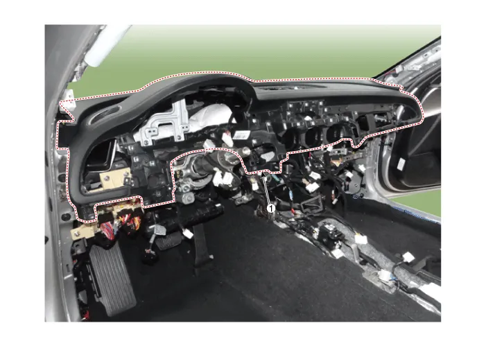
| 1. Main crash pad assembly
|
Repair procedures
| Replacement |
Put on gloves to protect your hands. |

|

| 1. |
Disconnect the negative (-) battery terminal. |
| 2. |
Remove the front seat assembly (both sides). (Refer to Front Seat - "Front Seat Assembly") |
| 3. |
Remove the floor console assembly. (Refer to Floor Console - "Floor Console Assembly") |
| 4. |
Remove the front pillar trim. (Refer to Interior Trim - "Front Pillar Trim") |
| 5. |
Remove the steering column shroud lower panel. (Refer to Crash Pad - "Steering Column Shroud Panel") |
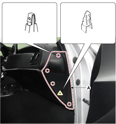
| 6. |
Remove the crash pad side cover [LH] (A) by using a remover.
|
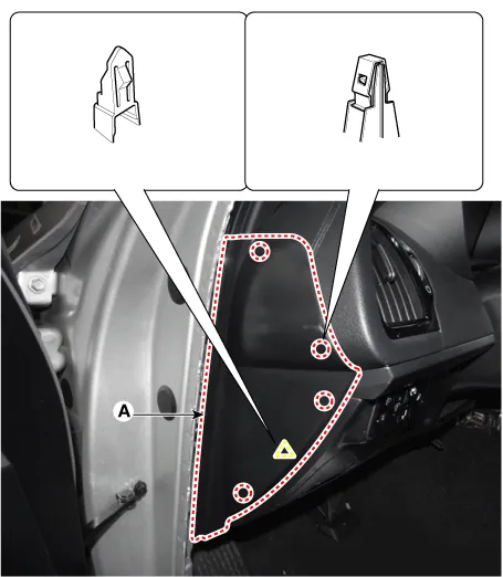
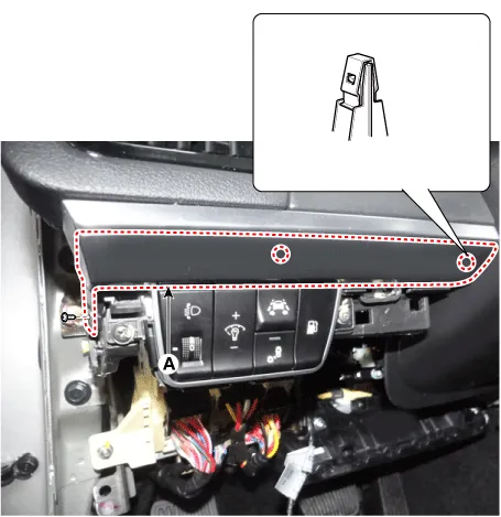
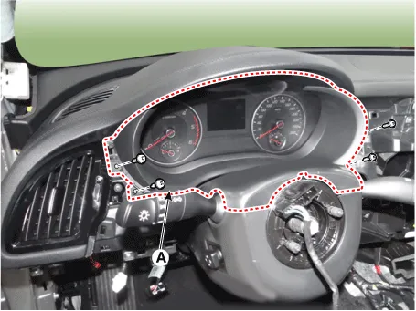
| 7. |
Separate the crash pad lower panel (A) after loosening the bolts and screws.
|
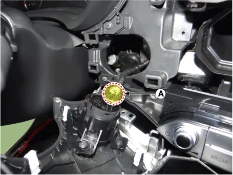
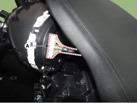
| 8. |
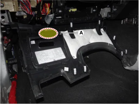
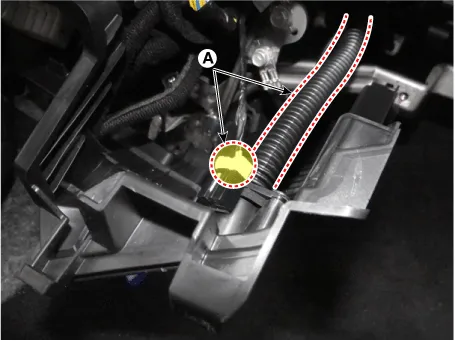
Disconnect the crash pad lower switch connector (A).
|
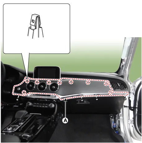
| 9. |
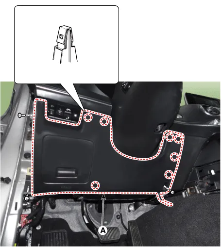
Remove the crash pad garnish [LH] (A) after loosening the mounting screws.
|
| 10. |
Remove the crash pad driver side panel (A) after loosening the mounting screws.
|

| 11. |
Remove the crash pad side cover [RH] (A) by using a remover.
|
| 12. |
Remove the crash pad garnish [RH] (A) after loosening the mounting screws.
|
| 13. |
Separate the crash pad passenger side panel (A) after loosening the mounting screws.
|
| 14. |
Disconnect the start/stop button connector (A) and then remove the crash pad garnish.
|
| 15. |
Remove the cluster fascia panel (A) by using a remover.
|
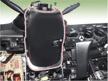
| 16. |
Remove the steering column shroud lower panel (A) after loosening the mounting screws.
|
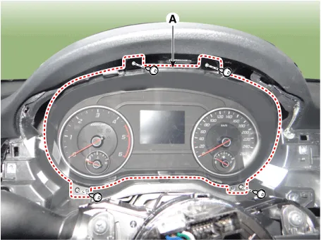
| 17. |
Separate the cluster (A) after loosening the mounting screws.
|
| 18. |
Remove the cluster assembly (A) after disconnecting the connector.
|
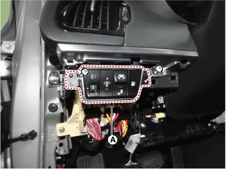
| 19. |
Remove the crash pad side switch (A) after loosening the screws.
|
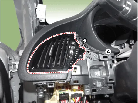
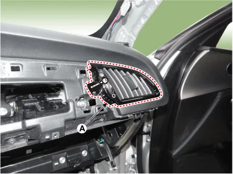
| 20. |
Remove the air vent duct (A) after loosening the screw. [LH]
[RH]
|
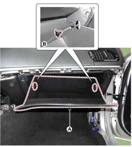
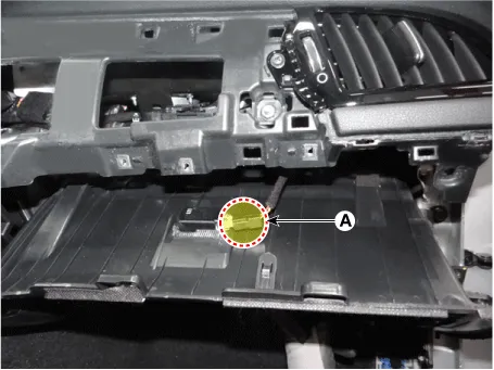
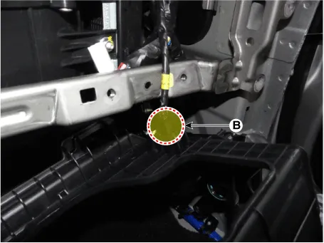
| 21. |
Pull out the both sides stopper (B) from the glove box (A).
|
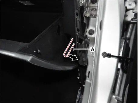
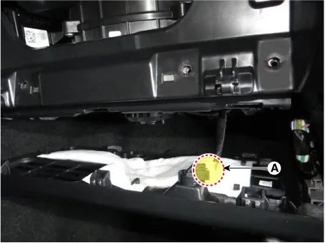
| 22. |
Remove the air damper (A) from the glove box (B).
|
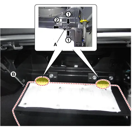
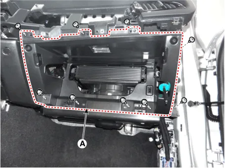
| 23. |
Remove the lock pins (A) and then remove the glove box (B).
|
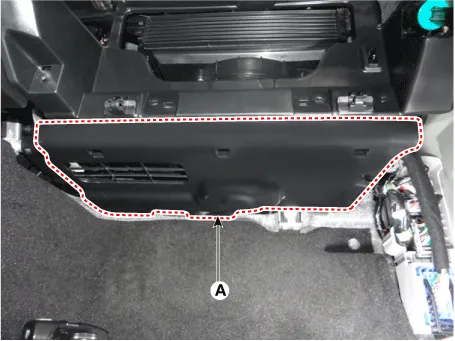
| 24. |
Separate the crash pad under cover [RH] (A).
|
| 25. |
Disconnect the lamp connector (A) and remove crash pad under cover.
|
| 26. |
Separate the glove box housing (A) after loosening the mounting screws, bolts, and nuts.
|
| 27. |
Remove the glove box housing after disconnecting the connector (A), (B).
|
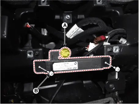
| 28. |
Remove the smart key antenna (B) after disconnecting the connector (A) and screws.
|
| 29. |
Separate the AVN head unit (A) after loosening the mounting screws.
|
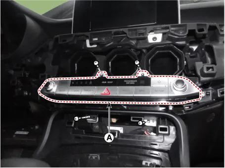
| 30. |
Remove the AVN head unit after disconnect the connectors (A).
|
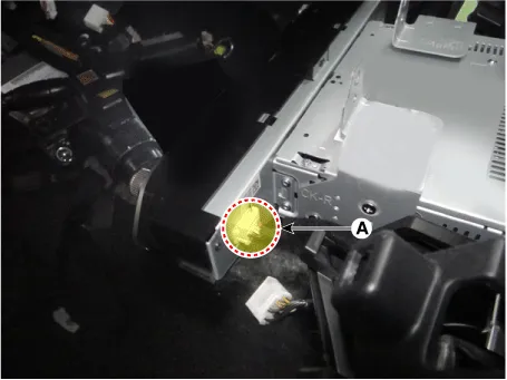
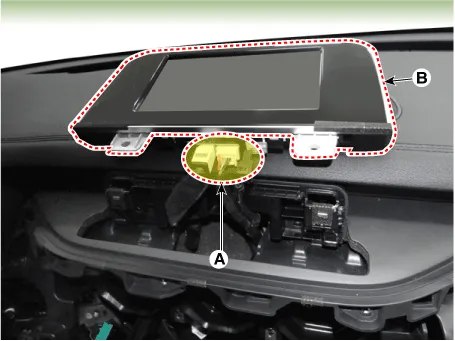
| 31. |
Separate the monitor assembly (A) after loosening the mounting screws.
|
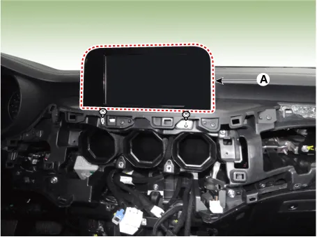
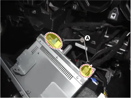
| 32. |
Remove the monitor assembly (A) after disconnect the connectors.
|
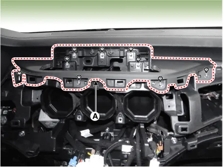
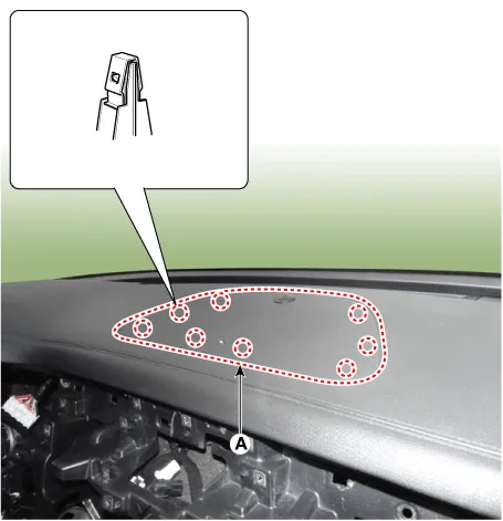
| 33. |
Remove the monitor fascia panel (A) after loosening the mounting screws.
|
| 34. |
Separate the center speaker grill (A) by using a remover.
|
| 35. |
Remove the center speaker grill after disconnecting the auto light photo sensor & security indicator connector (A).
|
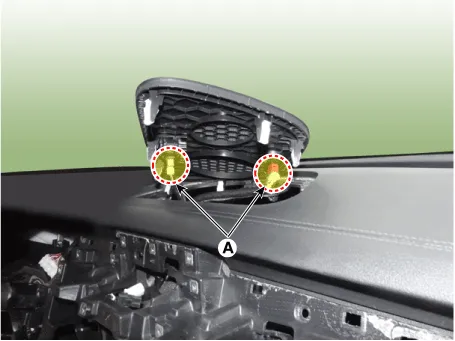
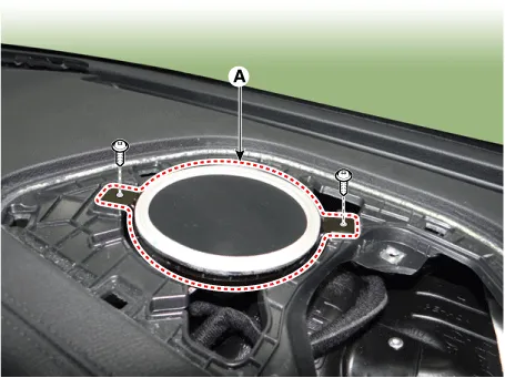
| 36. |
Separate the center speaker (A) after loosening the mounting screws.
|
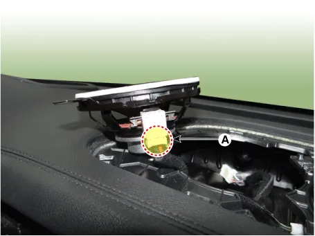
| 37. |
Remove the center speaker after disconnecting the connector (A).
|
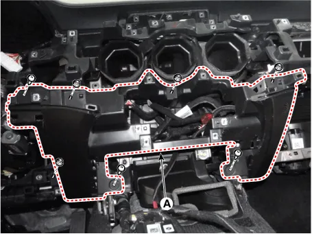
| 38. |
Separate the crash pad center lower cover (A) after loosening the mounting screws and nuts.
|
| 39. |
Remove the crash pad center lower cover after disconnecting the hose & connector (A).
|
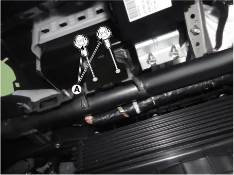
| 40. |
Loosen the passenger airbag module mounting bolts (A).
|
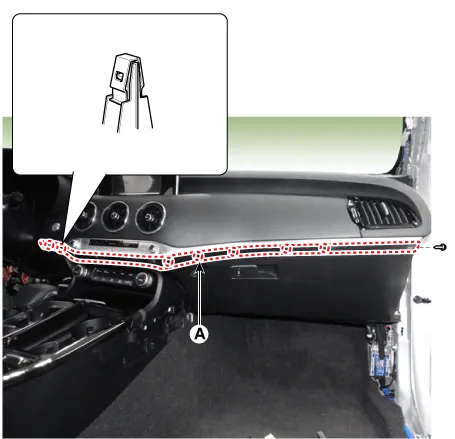
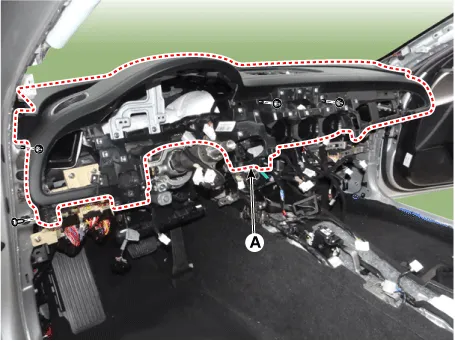
| 41. |
Separate the main crash pad assembly (A) after loosening the mounting bolts and nuts. [LH]
[RH]
|
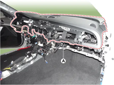
| 42. |
Remove the crash pad assembly after disconnecting the passenger airbag connector (A).
|

| 43. |
Install in the reverse order of removal.
|


Other information:
Kia Stinger (CK) 2018-2023 Service Manual: Parking Brake & Brake Fluid Warning Light
This warning light illuminates: Once you set the Engine Start/Stop Button to the ON position. - It illuminates for approximately 3 seconds When the parking brake is applied, the warning light will remain on. When the brake fluid level in the reservoir is low. - If the warning light illuminates with the parking brake released, it indicates the brake fluid level in reservoir is low.Kia Stinger (CK) 2018-2023 Service Manual: 7. Uniform tire quality grading
Quality grades can be found where applicable on the tire sidewall between tread shoulder and maximum section width. For example: TREADWEAR 440 TRACTION A TEMPERATURE A Tread wear The tread wear grade is a comparative rating based on the wear rate of the tire when tested under controlled conditions on a specified government test course. For example, a tire graded 150 would wear one-and-ahalf times (1½) as well on the government course as a tire graded 100.Categories
- Manuals Home
- Kia Stinger Owners Manual
- Kia Stinger Service Manual
- New on site
- Most important about car
