
Kia Stinger CK: Crash Pad / Cluster Fascia Panel
Components and components location
| Component Location |
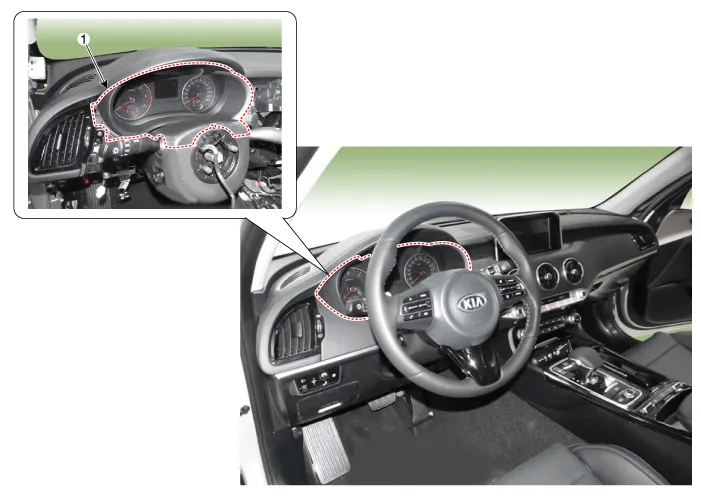
| 1. Cluster fascia panel |
Repair procedures
| Replacement |
Put on gloves to protect your hands. |

|

| 1. |
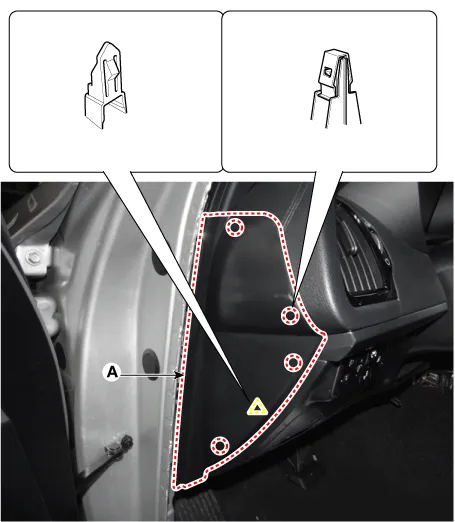
Remove the crash pad side cover [LH] (A) by using a remover.
|
| 2. |
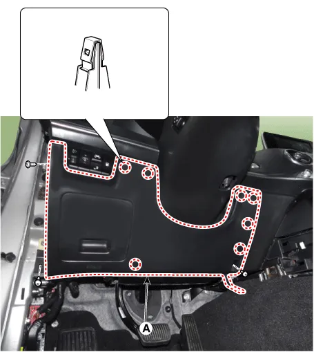
Separate the crash pad lower panel (A) after loosening the bolts and screws.
|
| 3. |
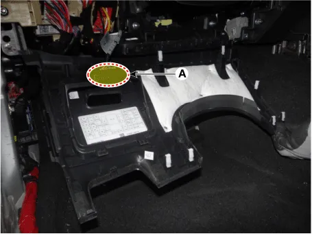
Disconnect the crash pad lower switch connector (A).
|
| 4. |
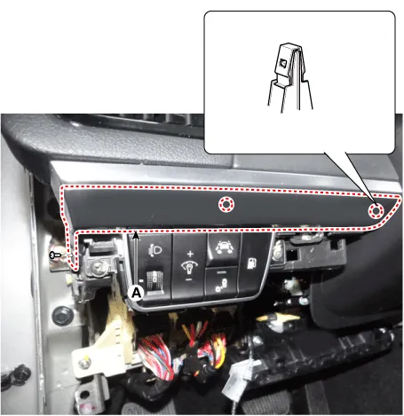
Remove the crash pad garnish [LH] (A) after loosening the mounting screws.
|
| 5. |
Remove the crash pad driver side panel (A) after loosening the mounting screws.
|

| 6. |
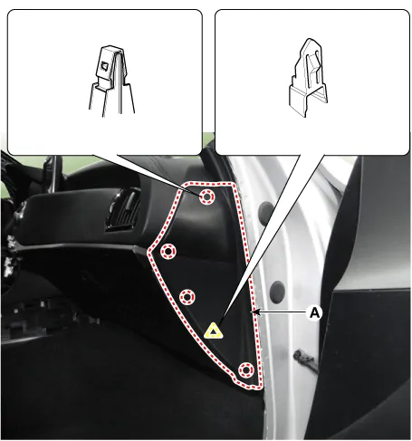
Remove the crash pad side cover [RH] (A) by using a remover.
|
| 7. |
Remove the crash pad garnish [RH] (A) after loosening the mounting screws.
|
| 8. |
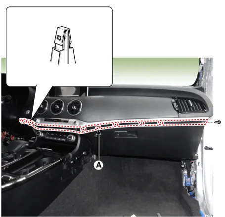
Separate the crash pad passenger side panel (A) after loosening the mounting screws.
|
| 9. |
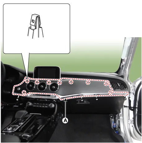
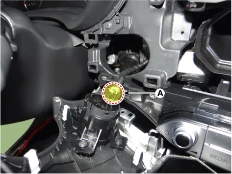
Disconnect the start/stop button connector (A) and then remove the crash pad garnish.
|
| 10. |
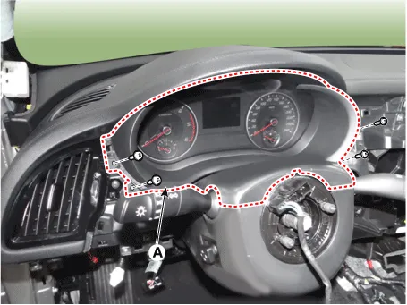
Remove the cluster fascia panel (A) by using a remover.
|
| 11. |
Install in the reverse order of removal.
|


Other information:
Kia Stinger (CK) 2018-2023 Service Manual: Around View Monitor (AVM) Unit
Components and components location Components Schematic diagrams Circuit Diagram Repair procedures Removal Put on gloves to protect your hands. • When prying with a flat-tip screwdriver or use a prying trim tool, wrap it with protective tape, and apply protective tape around the related parts, to prevent damage.Components and components location Components Schematic diagrams Circuit Diagram [Radio + GPS] [Radio + GPS + DAB] [Radio + GNSS + eCall] Repair procedures Removal AVN antenna 1. Disconnect the negative (-) battery terminal. 2. Remove the roof trim assembly.Categories
- Manuals Home
- Kia Stinger Owners Manual
- Kia Stinger Service Manual
- New on site
- Most important about car
