Kia Stinger CK: Smart Cruise Control (Stop & Go) System / Smart Cruise Control (Stop & Go) (SCC) Switch
Components and components location
| Components |
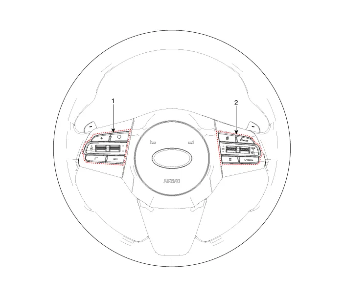
| 1. Left Remote Control Switch
(Audio + Bluetooth + Voice) |
2. Right Remote Control Switch
(Trip Computer + ACC + SCC) |
Schematic diagrams
| Circuit Diagram |
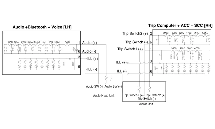
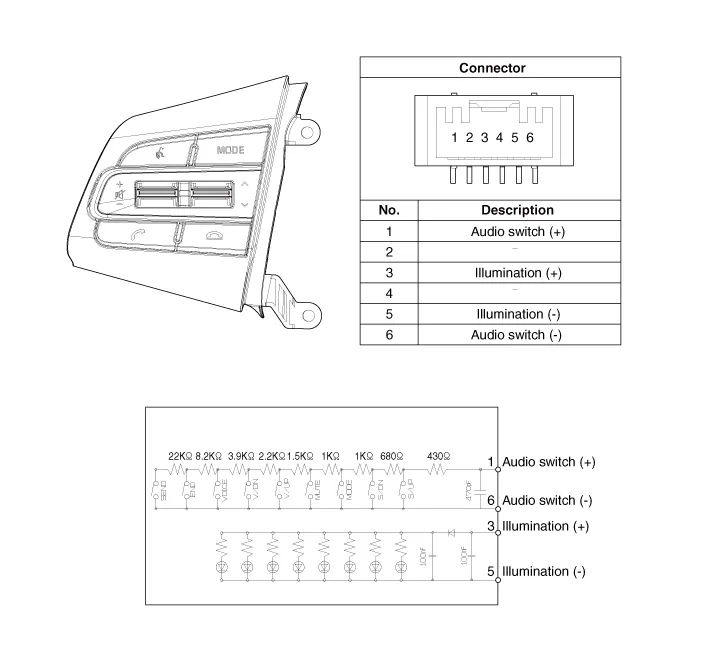
| [Audio + Bluetooth + Voice] |
| [Trip + ACC] |

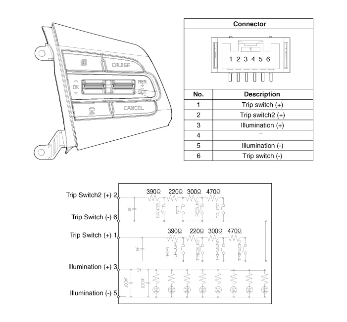
| [Trip + ACC + SCC] |
Repair procedures
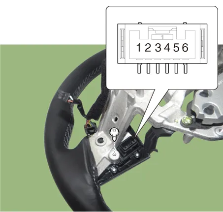
| Inspection |
| 1. |
Check for resistance between terminals in each switch position (RH).
[RH : Trip + ACC + SCC]
|
| Removal |
| 1. |
Disconnect the negative (-) battery terminal. |
| 2. |
Remove the steering wheel assembly. (Refer to Steering System - "Steering Wheel") |
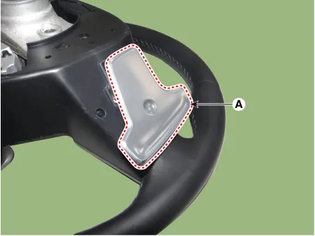
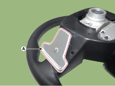
| 3. |
Remove the paddle shift switch (A) after loosening the mounting screws. [LH]
[RH]
|


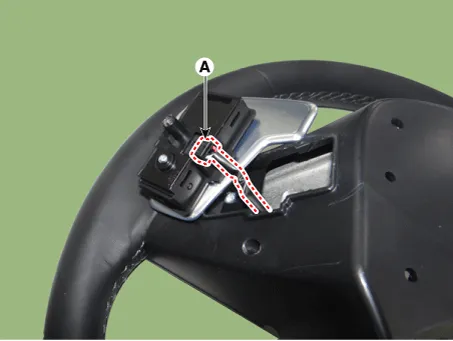
| 4. |
Disconnect the paddle shift switch connector (A). [LH]
[RH]
|

| 5. |
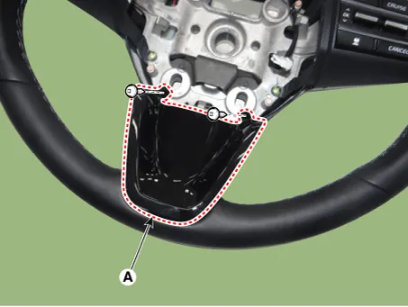
Remove the steering front cover (A) after loosening the mounting screws.
|
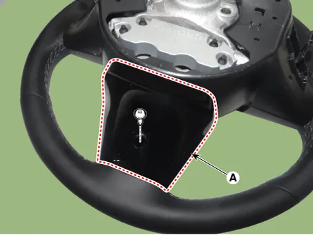
| 6. |
Remove the steering rear cover (A) after loosening the mounting screws.
|
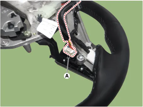
| 7. |
Remove the steering back cover (A) after loosening the mounting screws.
|

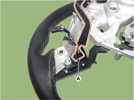
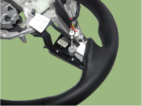
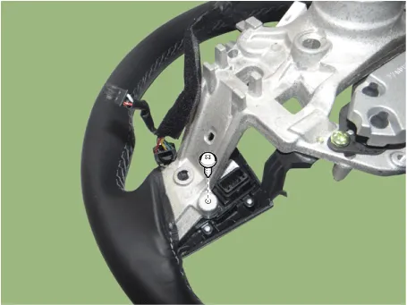
| 8. |
Disconnect the steering wheel remote control connector (A). [LH]
[RH]
|
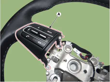
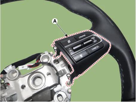
| 9. |
Remove the steering wheel remote control (A) after loosening the mounting screws. [LH]
[RH]
|
| Installation |
| 1. |
Install the steering wheel remote control. |
| 2. |
Connect the steering remote control connector. |
| 3. |
Install the steering back cover. |
| 4. |
Install the steering rear cover. |
| 5. |
Install the steering front cover. |
| 6. |
Connect the paddle shift switch connector. |
| 7. |
Install the paddle shift switch. |
| 8. |
Install the steering wheel assembly. |
| 9. |
Connect the negative (-) battery terminal. |


Other information:
Components and components location Components 1. Intercooler 2. Intercooler inlet hose & pipe 3. Intercooler outlet hose & pipe 4. Intercooler upper mounting insulator (RH) 5. Intercooler upper mounting bracket (RH) 6. Intercooler upper mounting insulator (LH) 7. Intercooler upper mounting bracket (LH) 8.Description and operation Description An ignition coil is an induction coil in an engine's ignition system which transforms the battery's low voltage to the high voltage needed to create an electric spark in the spark plugs to ignite the fuel. Coils have an internal resistor while others rely on a resistor wire or an external resistor to limit the current flowing into the coil from the battery 12 V supply.Categories
- Manuals Home
- Kia Stinger Owners Manual
- Kia Stinger Service Manual
- New on site
- Most important about car
