Kia Stinger CK: Smart Cruise Control (Stop & Go) System / Smart Cruise Control (Stop & Go) (SCC) ECU
Description and operation
| Description |
The smart cruise control unit is installed on the front right-hand side of the chassis. A radar sensor is embedded in the front section of the unit. This sensor detects vehicles and objects in front of the vehicle. The radar sensor can detect up to 64 objects ahead of the vehicle. The alarm goes off when the vehicle deviates from the horizontal and vertical alignment reference points during operation. This sensor communicates with the dashboard, warning buzzer, smart cruise control switch, Electronic Stability Program (ESP), ECM, and TCM via CAN communication. The sensor controls vehicle speed through CAN communication between the Electronic Stability Program (ESP) system and the ECM and TCM.
Schematic diagrams
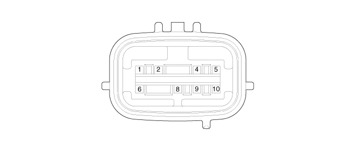
| Schematic Diagrams |
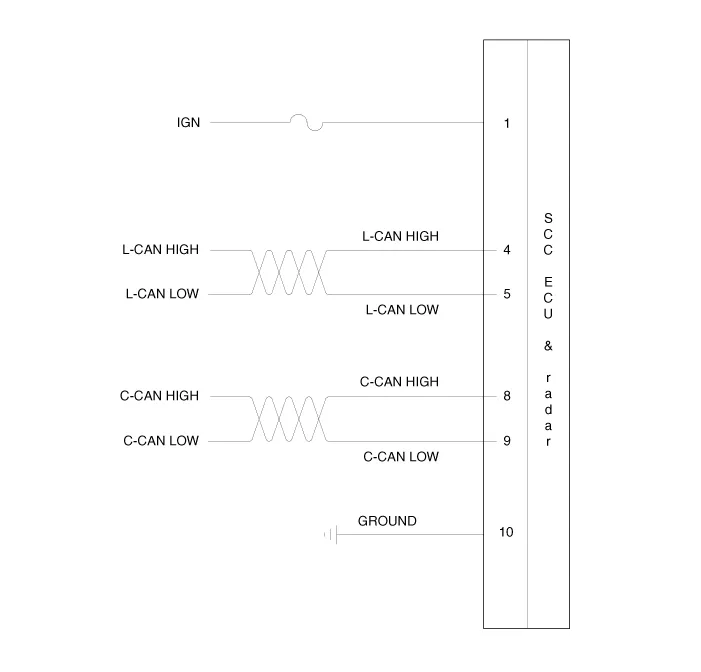
| Terminal function |
|
Pin No |
Terminal function |
|
1 |
IGN |
|
2 |
- |
|
3 |
- |
|
4 |
L-CAN HIGH |
|
5 |
L-CAN LOW |
|
6 |
- |
|
7 |
- |
|
8 |
C-CAN HIGH |
|
9 |
C-CAN LOW |
|
10 |
GROUND |
Repair procedures
| Removal |
| 1. |
Turn ignition switch OFF and disconnect the negative (-) battery cable. |
| 2. |
Remover the front bumbper assembly. (Refer to Body - "Front bumper assembly") |
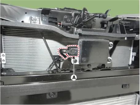
| 3. |
Disconnect the front radar connector (A).
|
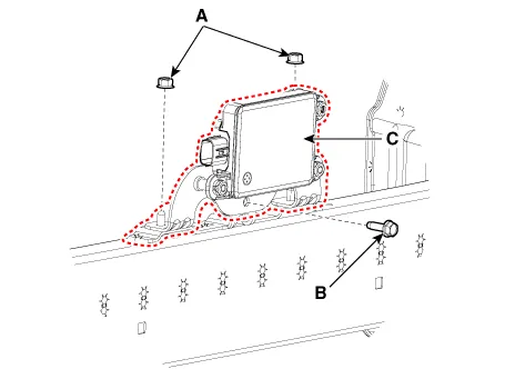
| 4. |
Loosen the front radar nuts (A) and bolt (B) and then remove the front radar (C).
|
| Installation |
| 1. |
Install in the reverse order of removal. |
| 2. |
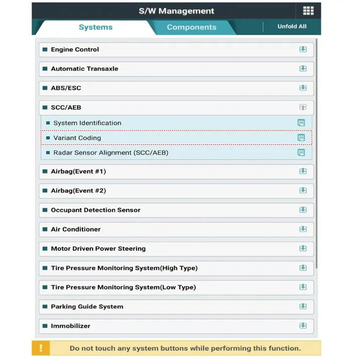
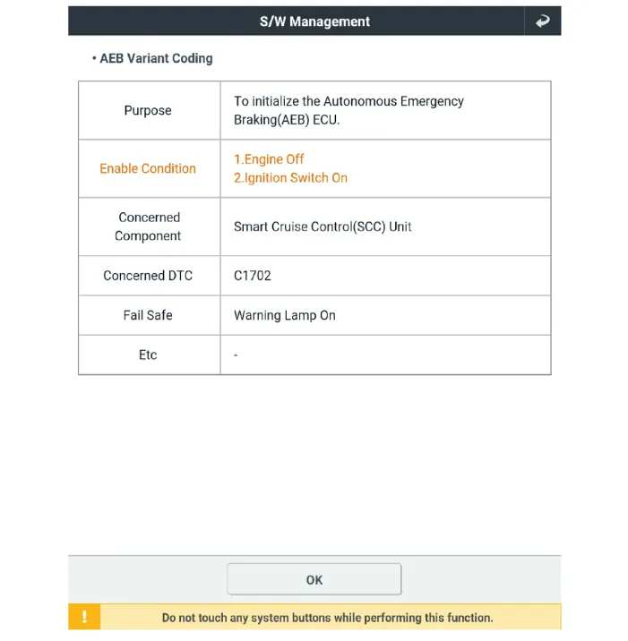
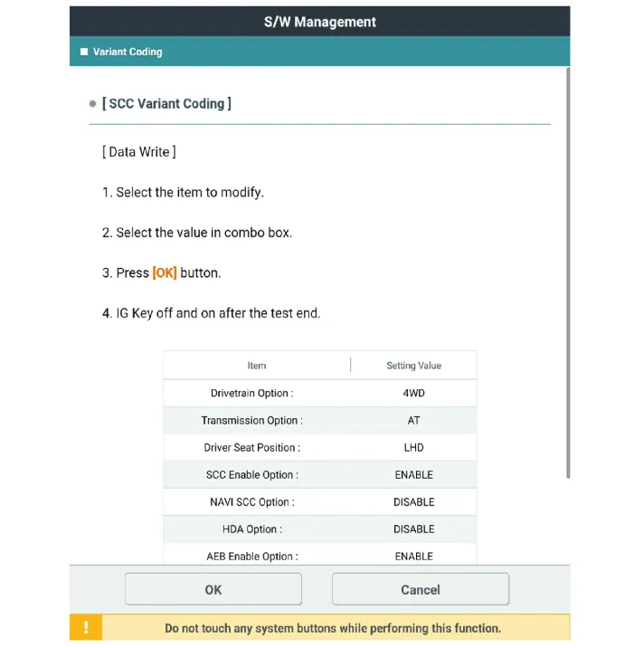
Perform SCC variant coding.
|
| 3. |
Perform the smart cuise control system (Stop & Go) unit radar alignment. (Refer to Engine Electrical System - "Smart cruise control (Stop & Go) unit-radar") |


Other information:
Kia Stinger (CK) 2018-2023 Service Manual: Vanity Lamp
Repair procedures Removal 1. Disconnect the negative (-) battery terminal. 2. Remove the vanity lamp (A) using a flat-tip screwdriver. 3. Disconnect the vanity lamp connector (A). Installation 1. Connect the vanity lamp connector.Kia Stinger (CK) 2018-2023 Service Manual: Seat Belt Buckle Switch (BS)
Description and operation Description The SRSCM shall monitor the status of the driver and front passenger seat belt buckle. The SRSCM provides one pin each for the driver and front passenger seat belt buckle status input. The seat belt buckle circuit operates from internal boost voltage supplied by the SRSCM, and uses chassis ground for the signal return.Categories
- Manuals Home
- Kia Stinger Owners Manual
- Kia Stinger Service Manual
- New on site
- Most important about car
