Kia Stinger CK: Body Electrical System / Horn
Components and components location
| Component Location |
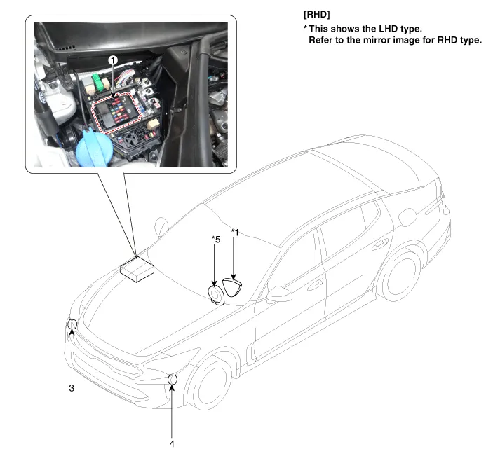
| 1. Horn switch 2. Horn relay (Built - in Metal Core Block PCB) 3. Horn (Low pitch) |
4. Horn (High pitch) 5. Clock spring |
Repair procedures
| Removal |
| 1. |
Remove the front bumper assembly. (Refer to Body - "Front Bumper Assembly") |
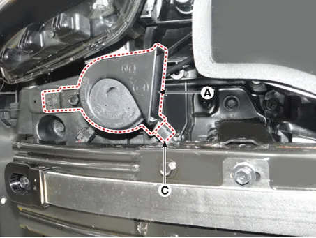
| 2. |
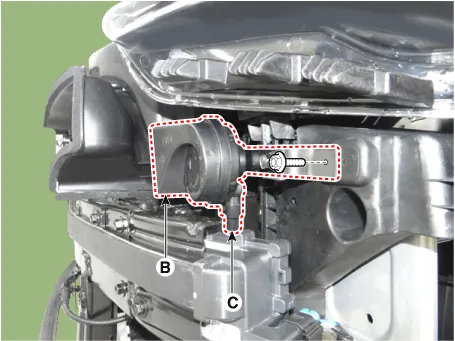
After loosening each mounting bolt of the low-pitch horn (A) and high-pitch horn (B), detach the connector (C) and remove the horn. [Low - Pitch Horn]
[High - Pitch Horn]
|
| Installation |
| 1. |
After connecting the horn connectors, install both high-pitch and low-pitch horns. |
| 2. |
Install the front bumper assembly. |
| Inspection |
| 1. |
The relay on the horn of this vehicle is implanted into the metal core block PCB of the engine room relay block. |
The semi-conductor type relay inserted in the PCB is impossible to replace. If the relay needs to be replaced, replace the metal core box and conduct a test on it. |


Other information:
Kia Stinger (CK) 2018-2023 Service Manual: Specifications
Service data Service Data Item Specification Product name Transfer case Operation method Electronic actuator control method (DC motor) Torque capacity 1,000 Nm Weight 24.8 kg (Oil injection state) Tightening torque Tightening Torques Item N·m Kgf·m lb·ft Bolt for fixing the transfer case 29.Kia Stinger (CK) 2018-2023 Service Manual: Inside Rear View Mirror
Components and components location Component Location 1. Inside rear view mirror Repair procedures Replacement Put on gloves to protect your hands. • Use a plastic panel removal tool to remove interior trim pieces without marring the surface.Categories
- Manuals Home
- Kia Stinger Owners Manual
- Kia Stinger Service Manual
- New on site
- Most important about car
