Kia Stinger CK: Headlamp Leveling System / Headlamp Leveling Unit
Components and components location
| Circuit Diagram |

Description and operation
| Description |
According to driving environment and loading state of vehicle, headlamp lighting direction is changed to keep the driver's visibility range and to protect the driver's vision from glare, aiming at safety driving.
Sensor integrated ECU mounted on the rear center arm drives the actuator mounted on the headlamp after sensing the input signal for the static change of vehicle.
Headlamp beam is automatically operated by chassis tilt.
| Operation |
Operating Procedure
| 1. |
Suspension angle change resulted from vehicle's load change. |
| 2. |
Sensor angle change. |
| 3. |
Microprocessor calculates necessary headlamp angle change amount. |
| 4. |
Sending a proper signal to headlamp leveling device and driving actuator. |
Operating Condition
| 1. |
Ignition on |
| 2. |
Low beam on |
| 3. |
On stop : If sensor lever change is 0.3° and above, headlamps are operated after max. 1.5 seconds. |
| 4. |
On driving : If vehicle velocity is over 4 km/h (2.48 mph), velocity change is not over 0.8 - 1.6 km/h (0.5 - 1.0 mph) per second, and loading condition is changed, then headlamps are operated. |
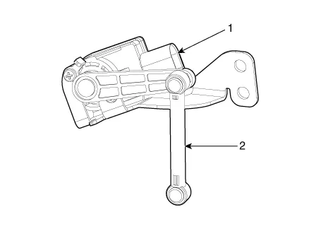
Components
| 1. |
Auto headlamp leveling unit
|
Repair procedures
| Inspection |
| 1. |
Ignition "ON". |
| 2. |
Turn on the headlamp switch. |
| 3. |
Check for operation. The aim of the headlamps should change smoothly when the headlamp leveling switch is operated. |
| 4. |
If the operation does not work well, inspect the connector and terminals to be sure they are all making good contact. If the terminals are bent, loose or corroded, repair them as necessary, and recheck the system. If the terminals look OK, go to step 5. |
| 5. |
Substitute with a known-good headlamp assembly and check for proper operation. |
| Removal |
| 1. |
Disconnect the negative (-) battery terminal. |
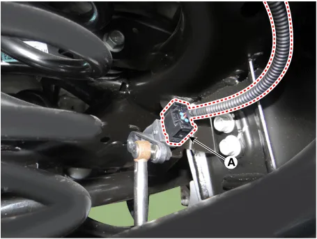
| 2. |
Disconnect the headlamp leveling unit connector (A).
|
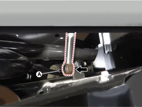
| 3. |
Remove the headlamp leveling unit mounting link (A).
|
| 4. |
Remove the headlamp leveling unit (A) after loosening the mounting bolts.
|

| Installation |
| 1. |
Install the headlamp leveling unit.
|
| 2. |
Install the headlamp leveling unit mounting link. |
| 3. |
Connect the headlamp leveling unit connector. |
| 4. |
Connect the negative (-) battery terminal. |


Other information:
Components and components location Components 1. Front seat back covering 2. Front seat back pad 3. Front seat back heater 4. Front seat back ventilation mat 5. Front seat headrest 6. Front seat headrest guide 7. Front seat back air duct 8. Front seat back board 9. Front seat SAB module 10.Service data Service Data Fuel Delivery System Items Specification Fuel Tank Capacity 60 L (15.8 U.S.gal., 63.4 U.S.qt., 52.7 Imp.qt.) Fuel Filter Type Paper type Fuel Pressure Low Pressure Fuel Line Over 290 kPa (Over 2.Categories
- Manuals Home
- Kia Stinger Owners Manual
- Kia Stinger Service Manual
- New on site
- Most important about car
