Kia Stinger CK: Manual heating and air conditioning / Mode selection

The mode selection button controls the direction of the air flow through the ventilation system.
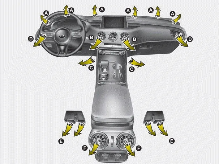
The air flow outlet port is converted as follows:

Face-Level (B, D, F)

Air flow is directed toward the upper body and face. Additionally, each outlet can be controlled to direct the air discharged from the outlet.
Bi-Level (B, C, D, E, F)

Air flow is directed towards the face and the floor.
Floor-Level (A, C, E, F)

Most of the air flow is directed to the floor, with a small amount of the air being directed to the windshield and side window defrosters.
Floor/Defrost-Level (A, C, D, E, F)

Most of the air flow is directed to the floor and the windshield with a small amount directed to the side window defrosters.
Defrost-Level

Most of the air flow is directed to the windshield with a small amount of air directed to the side window defrosters.
Instrument panel vents
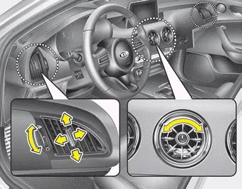
The outlet vents can be opened or closed separately using the thumbwheel (if equipped).
Also, you can adjust the direction of air delivery from these vents using the vent control lever as shown.


Other information:
Kia Stinger (CK) 2018-2023 Owner's Manual: Crankshaft
Repair procedures Disassembly In case of removing the high pressure fuel pump, high pressure fuel pipe, delivery pipe, and injector, there may be injury caused by leakage of the high pressure fuel. So don’t do any repair work right after engine stops. • Use fender covers to avoid damaging painted surfaces.Kia Stinger (CK) 2018-2023 Owner's Manual: Fuel Pressure Control Valve (FPCV)
Specifications Specification Item Specification Coil Resistance (Ω) 0.47 - 0.53 [20°C(68°F)] Description and operation Description Installed on the high pressure fuel pump, the Fuel Pressure Control Valve controls flow of fuel into the injectors in accordance with the ECM signal calculated based on various engine conditions.Categories
- Manuals Home
- Kia Stinger Owners Manual
- Kia Stinger Service Manual
- New on site
- Most important about car
