Kia Stinger CK: Automatic transmission (shift-by-wire) / LCD display messages
Contents:
- Shifter Malfunction
- Check shift lever
- Shifting conditions not met
- Press brake pedal to change gear
- Shift to P after stopping
- Press UNLOCK to change gear
- PARK engaged
- NEUTRAL engaged
Shifter Malfunction

The warning message appears on the LCD display, when the transmission or the shift lever does not properly operate in the P (Park) position. In this case, we recommend you to immediately have the vehicle inspected by an authorized Kia dealer.
Check shift lever
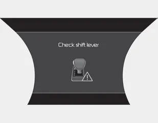
The warning message appears on the LCD display, when there is a malfunction with one of the key transmission components.
In this case, have the vehicle inspected by an authorized Kia dealer immediately.
Shifting conditions not met

The warning message appears on the LCD display, when engine RPM is too high, or when driving speed is too fast to shift the gear.
We recommend you decrease your RPM level or slow down before shifting the gear.
Press brake pedal to change gear

The warning message appears on the LCD display, when the brake pedal is not depressed while shifting the gear.
We recommend you depress the brake pedal and then shift the gear.
Shift to P after stopping
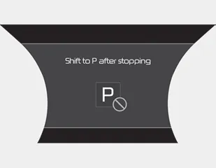
The warning message appears on the LCD display, when the brake pedal is not depressed while shifting the gear.
We recommend you depress the brake pedal and then shift the gear.
Press UNLOCK to change gear

The warning message appears on the LCD display, when the [UNLOCK] button is not pressed while shifting the gear.
We recommend you press the [UNLOCK] button and then shift the gear.
PARK engaged

The message appears on the LCD display, when the P (Park) position is engaged.
NEUTRAL engaged
The message appears on the LCD display, when the N (Neutral) position is engaged.


Other information:
Repair procedures Removal 1. Remove wheel nuts, wheel and tire (A) from hub. Tightening torque: 107.9 - 127.5 N·m (11.0 - 13.0 kgf·m, 79.6 - 94.0 lb·ft) Be careful not to damage the wheel bolts when removing the wheel and tire (A).Components and components location Component Location 1. Front console armrest Repair procedures Replacement Put on gloves to protect your hands. • Use a plastic panel removal tool to remove interior trim pieces without marring the surface.Categories
- Manuals Home
- Kia Stinger Owners Manual
- Kia Stinger Service Manual
- Shifter Malfunction
- Check shift lever
- Shifting conditions not met
- Press brake pedal to change gear
- Shift to P after stopping
- Press UNLOCK to change gear
- PARK engaged
- NEUTRAL engaged
- New on site
- Most important about car
Contents
