Kia Stinger CK: Seat Electrical / Power Seat Control Switch
Repair procedures
| Inspection |
Diagnosis With KDS
| 1. |
The body electrical system can be quickly diagnosed for failed parts by using the vehicle diagnostic system (KDS). The diagnostic system (KDS) provides the following information.
|
| 2. |
Select the 'Car model' and the system to be checked in order to check the vehicle with the tester. |
| 3. |
Select the 'Power seat module (PSM)' to check the power seat module (PSM). |
| 4. |
Select the 'Current data' menu to check the current state of the input/output data. The input/output data for the sensors corresponding to the power seat module (PSM) can be checked. |
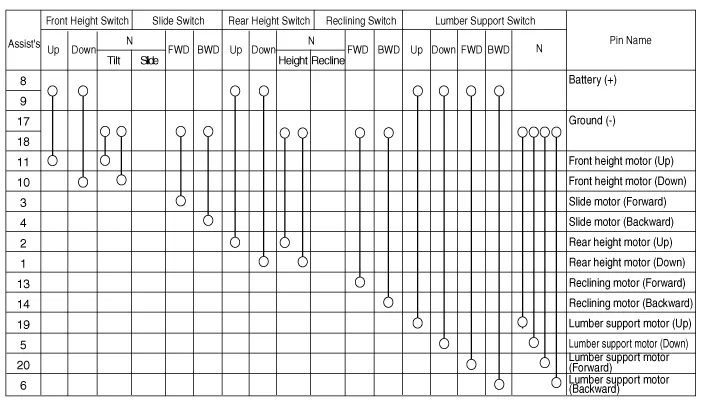
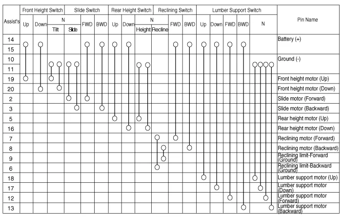
Seat Control Switch
| 1. |
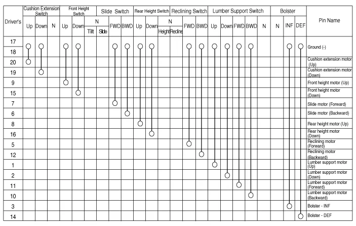
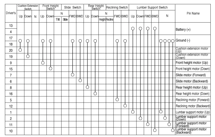
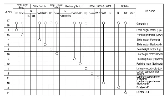
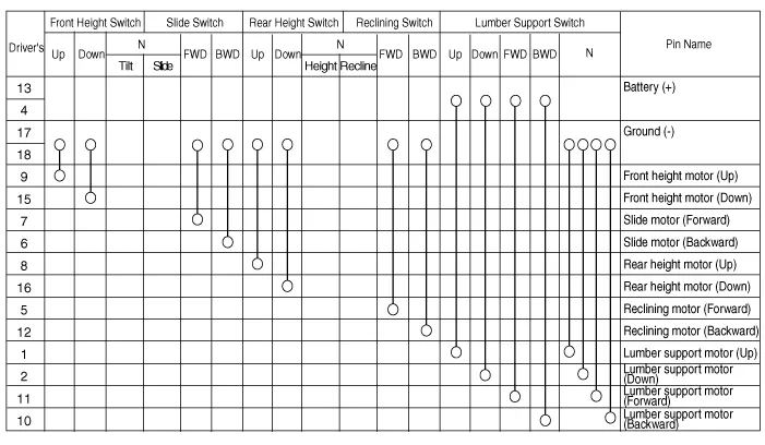
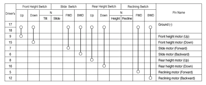
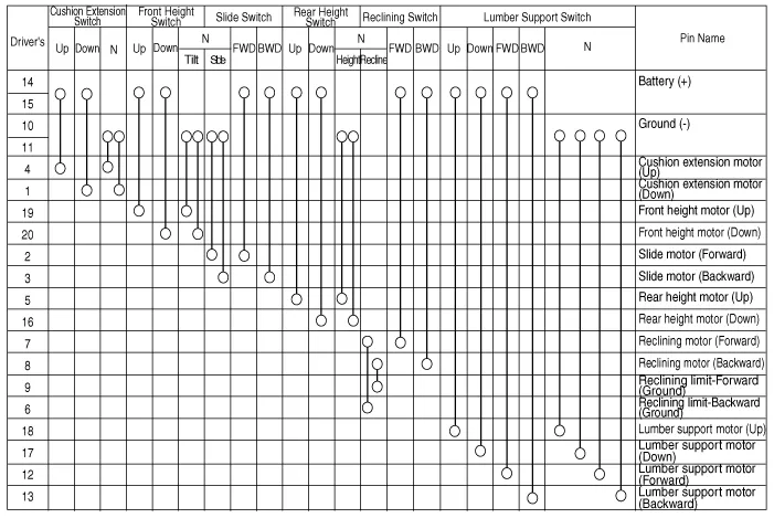
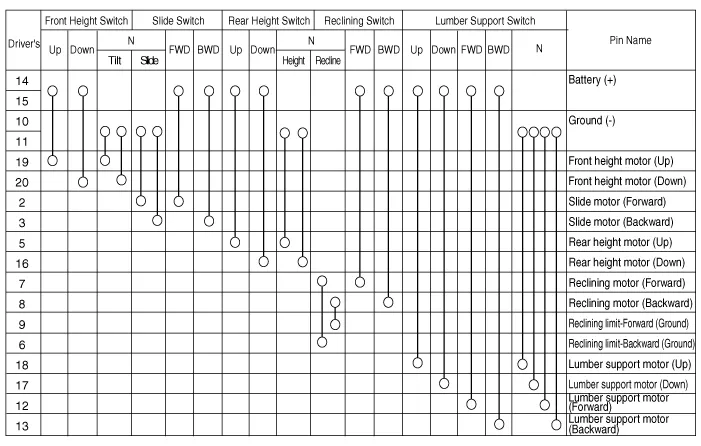
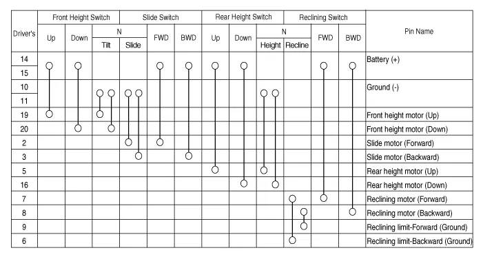
With the power seat switch in each position, make sure that continuity exists between the terminals below. If continuity is not as specified, replace the power seat switch.
|

Driver's Seat / IMS Type
| [16Way (EXT + Bolster) Type] |
| [14Way (EXT) Type] |
| [14Way (SLB) Type] |
| [12Way Type] |
| [8Way Type] |
Driver's Seat / Non-IMS Type
| [14Way (EXT) Type] |
| [12Way Type] |
| [8Way Type] |
Assist's Seat / Non-IMS Type
| [12Way (Walk-In) Type] |
| [12Way Type] |
| [8Way Type] |

| Removal |
| 1. |
Disconnect the negative (-) battery terminal. |
| 2. |
Remove the front seat outer shield cover. (Refer to Body - "Front Seat Outer Shield Cover") |
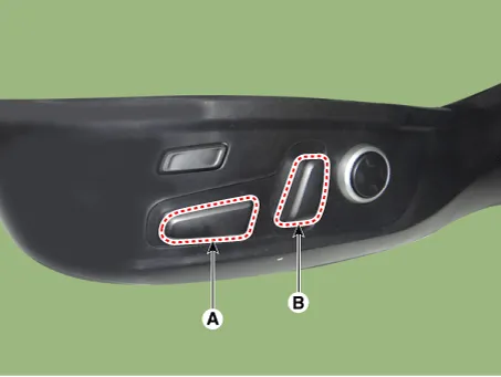
| 3. |
Remove the slide knob (A) and reclining knob (B).
|
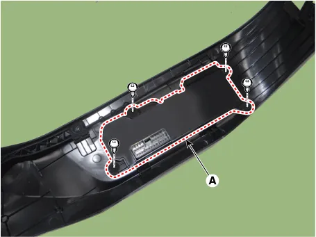
| 4. |
Remove the power seat control switch (A) after loosening the mounting screws.
|
| Installation |
| 1. |
Install the power seat control switch. |
| 2. |
Install the slide knob and reclining knob. |
| 3. |
Install the front seat outer shield cover. |
| 4. |
Connect the negative (-) battery terminal. |


Other information:
Kia Stinger (CK) 2018-2023 Service Manual: Automatic Transmission System
Components and components location Components 1. Torque converter 2. Electric Oil Pump (EOP) 3. Parking switch (Inhibitor switch) 4. Main connector 5. ATF Warmer Repair procedures Removal 1. Disconnect the negative (-) battery terminal. 2. Remove the stay (A) by loosening the bolts.Kia Stinger (CK) 2018-2023 Service Manual: Front Seat Cushion Cover
Components and components location Component Location 1. Front seat cushion cover Repair procedures Replacement Put on gloves to protect your hands. • Use a plastic panel removal tool to remove interior trim pieces without marring the surface.Categories
- Manuals Home
- Kia Stinger Owners Manual
- Kia Stinger Service Manual
- New on site
- Most important about car
