Kia Stinger CK: Seat Electrical / Power Seat Motor
Components and components location
| Component Location |
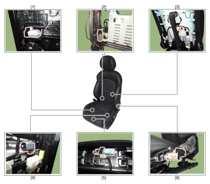
| 1. Slide motor 2. Reclining motor 3. Lumber support motor |
4. Front height motor 5. Cushion extension motor 6. Rear height motor |
Description and operation
| Description |
Power seat motor is driven by a motor in the following.
| 1. |
Slide motor |
| 2. |
Front height motor |
| 3. |
Rear height motor |
| 4. |
Reclining motor |
| 5. |
Cushion extension motor
|

Repair procedures
| Inspection |
Power Seat Motor
| 1. |
Disconnect the negative (-) battery terminal. |
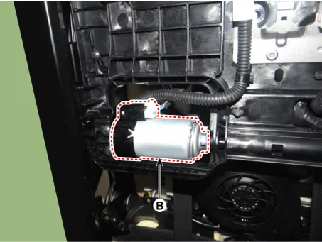
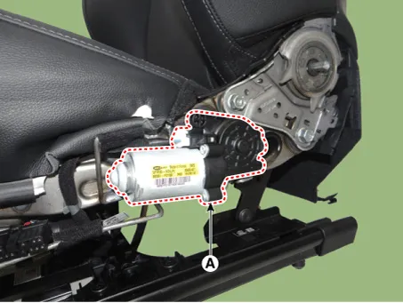
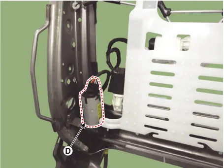
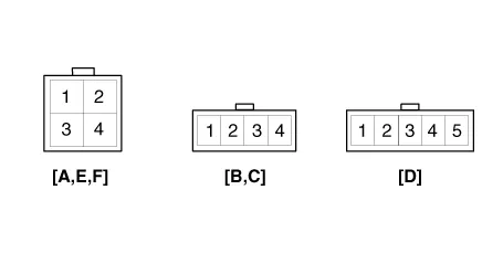
| 2. |
Disconnect the connectors for each motor. A : Front height motor
B : Slide motor
C : Rear height motor
D : Reclining motor
E : Cushion extension motor
F : Lumber support motor
|


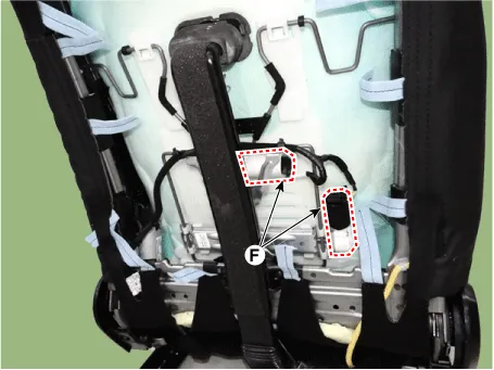
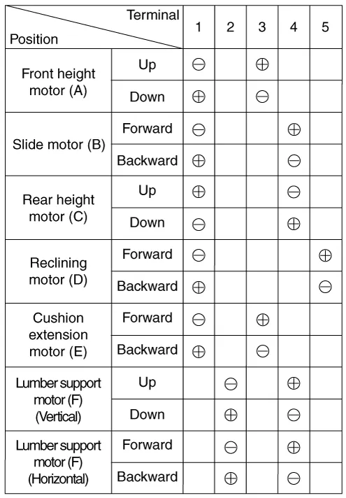
| 3. |
When the battery power is supplied to the motor connector, check the motor for smooth operation. |
| 4. |
Reverse the connections and check that the motor turns in reverse. |
| 5. |
If the motor runs abnormally, replace it.
[Driver]
[Assist]
|

| Remove |
Front Seat
| 1. |
Disconnect the negative (-) battery terminal. |
| 2. |
Remove the front seat assembly. (Refer to Body - "Front Seat Assembly") |


Other information:
Kia Stinger (CK) 2018-2023 Service Manual: Intake Air Temperature Sensor (IATS)
Specifications Specification Temperature Resistance (kΩ) °C °F -40 -40 40.93 - 48.35 -20 -4 13.89 - 16.03 0 32 5.38 - 6.09 10 50 3.Kia Stinger (CK) 2018-2023 Service Manual: Evaporator Temperature Sensor
Description and operation Description The evaporator temperature sensor detects the evaporator core temperature and interrupts compressor relay power in order to prevent evaporator from freezing by excessive cooling. Repair procedures Inspection 1. Turn the ignition switch OFF. 2. Disconnect the evaporator temperature sensor connector.Categories
- Manuals Home
- Kia Stinger Owners Manual
- Kia Stinger Service Manual
- New on site
- Most important about car
