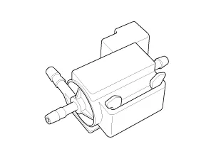
Installed on the intercooler inlet pipe, the RCV (Recirculation Valve) Control
Solenoid Valve operates the RCV actuator which controls the by-pass passage of the
turbocharger compressor. When the throttle is closed with the engine running at
cruise rpm (tip-out), the turbocharger boost pressure increases rapidly. The pressure
wave strikes a compressor blades causing a knocking noise. To prevent this, the
ECM opens the recirculation valve which allows excessive boost pressure to vent
back to the air cleaner side of the turbocharger compressor.
Other information:
Kia Stinger (CK) 2018-2023 Service Manual: Emission control system
The emission control system of your vehicle is covered by a written limited warranty.
Please see the warranty information contained in the Warranty & Consumer Information
manual in your vehicle.
Your vehicle is equipped with an emission control system to meet all applicable
emission regulations.
There are three emission control systems, as follows.
Kia Stinger (CK) 2018-2023 Service Manual: ISG (Idle Stop and Go) system
Your vehicle may be equipped with the ISG system, which reduces fuel consumption
by automatically shutting down the engine, when the vehicle is at a standstill.
(For example : red light, stop sign and traffic jam)
The engine starts automatically as soon as the starting conditions are met.
The ISG system is ON whenever the engine is running.
✽ NOTICE
When the engine automatically starts by the ISG system, some warning lights
(ABS, ESC, ESC OFF, EPS or Parking brake warning light) may turn on for a few seconds.