Kia Stinger CK: Fuses / Fuse/relay panel description
Contents:
■ Driver’s side fuse panel

■ Engine compartment fuse panel
■ Rear fuse box panel
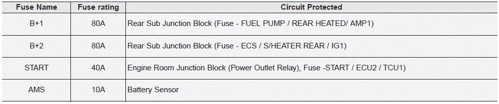
■ Battery box fuse panel
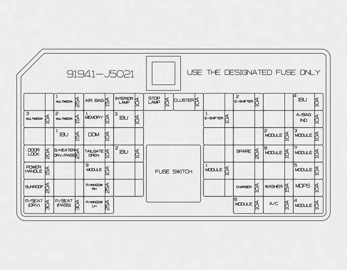
Inside the fuse/relay panel covers, you can find the fuse/relay label describing fuse/relay name and capacity.
✽ NOTICE
Not all fuse panel descriptions in this manual may be applicable to your vehicle. It is accurate at the time of printing. When you inspect the fuse panel in your vehicle, refer to the fuse panel label.
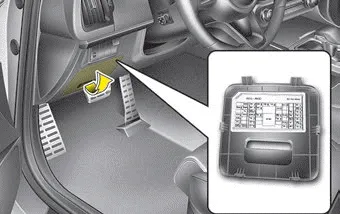
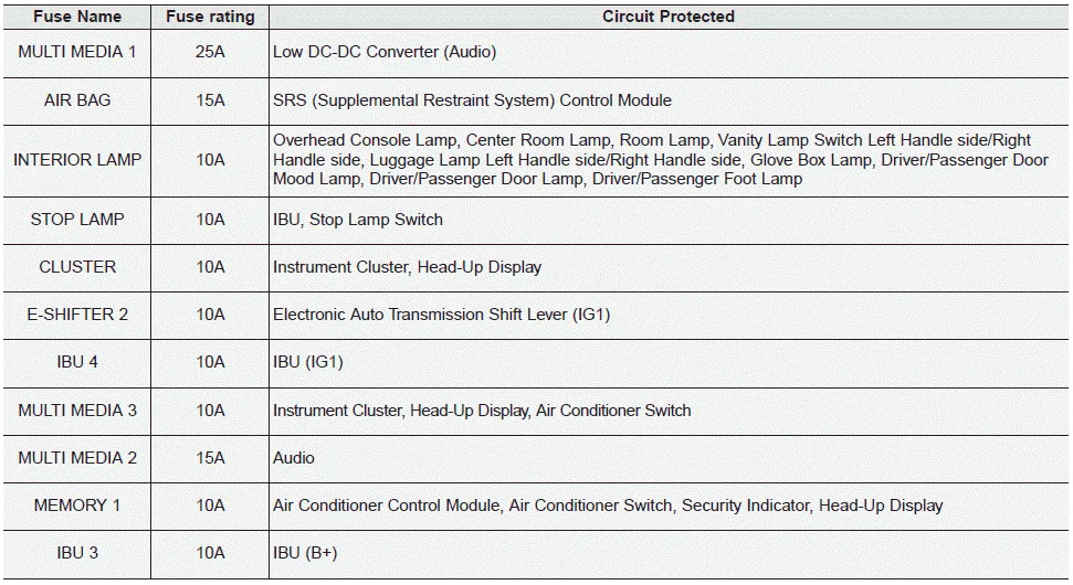
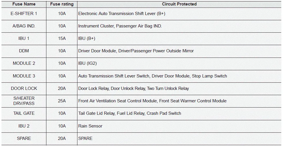
Driver’s side fuse panel
Instrument panel (Driver’s side fuse panel)
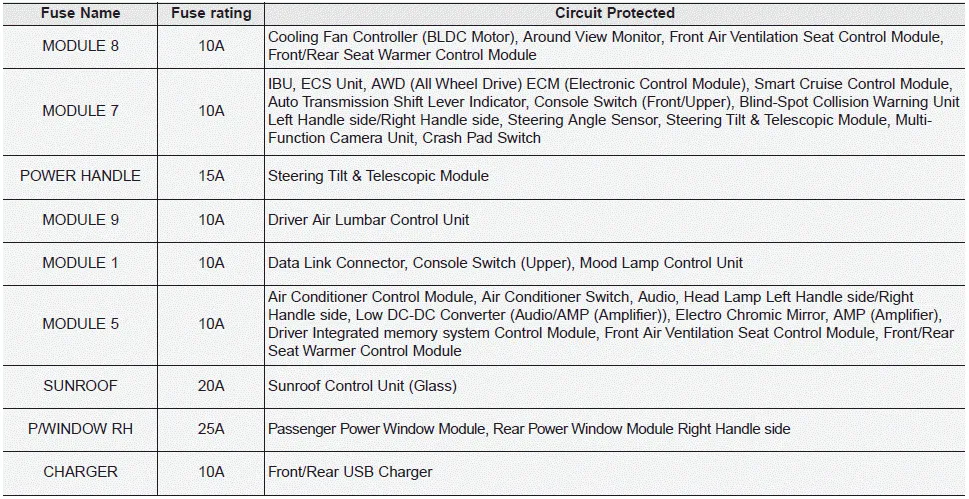

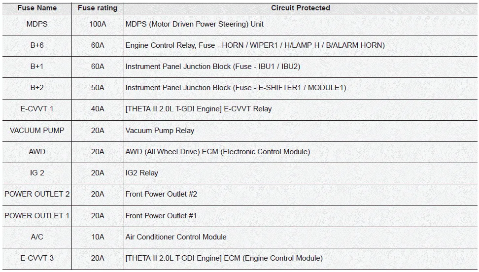
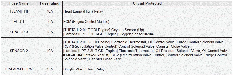
Engine compartment fuse panel
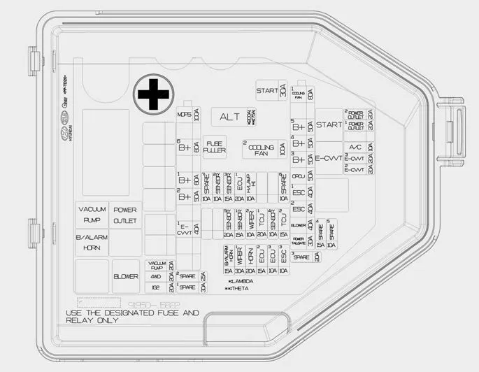
Engine room compartment fuse panel


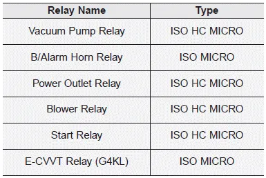
Relay
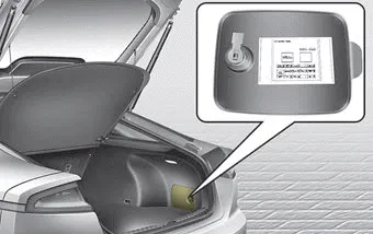
Rear fuse box panel
Rear fuse box panel

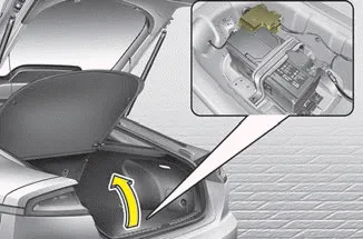
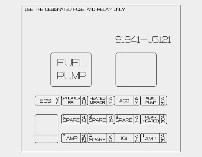
Battery box fuse panel
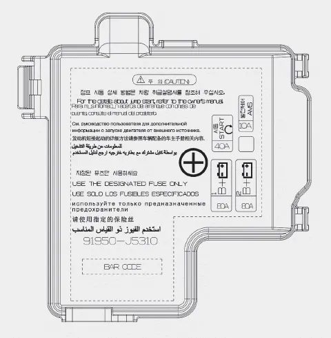
Battery box fuse panel


Other information:
Kia Stinger (CK) 2018-2023 Owner's Manual: AGM Battery
Specifications Specification ▷CMF90L-DIN Item Specification Model type CMF90L-DIN Capacity [20HR/5HR] (AH) 90/72 Cold Cranking Amperage (A) 740 (SAE) / 740 (EN) Reserve Capacity (Min) 170 ▷MF90L-DIN : Operable Item Specification Model type MF90L-DINKia Stinger (CK) 2018-2023 Owner's Manual: Windshield wipers
Operates as follows when the ignition switch is turned ON. MIST : For a single wiping cycle, move the lever to this (MIST) position and release it. The wipers will operate continuously if the lever is held in this position. OFF : Wiper is not in operation INT : Wiper operates intermittently at the same wiping intervals. Use this mode in light rain or mist.Categories
- Manuals Home
- Kia Stinger Owners Manual
- Kia Stinger Service Manual
- New on site
- Most important about car
Contents

Copyright © 2026 www.kstinger.com 0.0106