Kia Stinger CK: Seat Electrical / Seat Ventilation Unit
Components and components location
| Component Location |
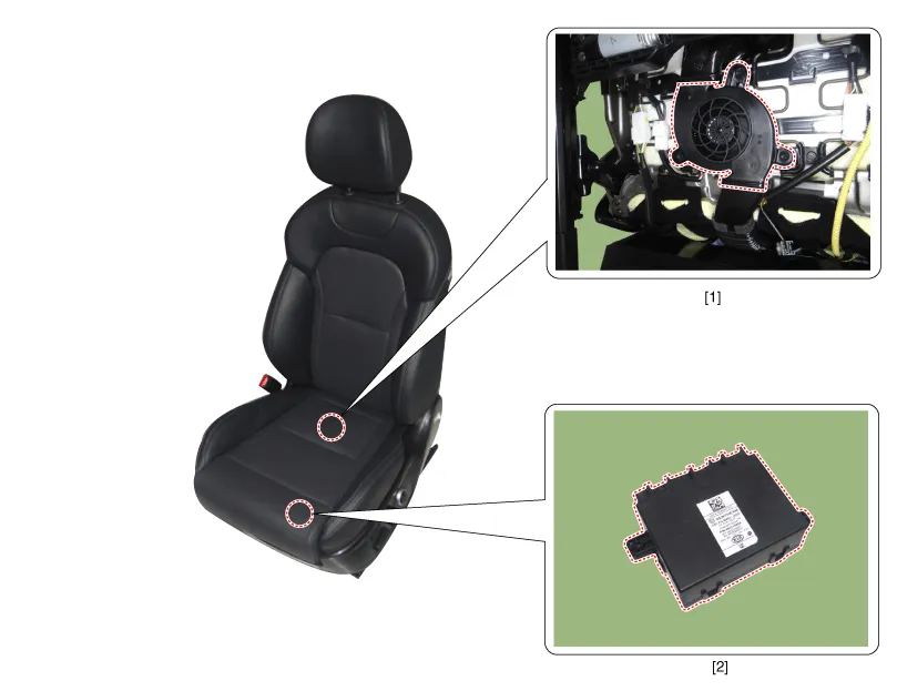
| 1. Seat ventilation blower
|
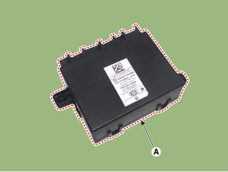
2. Seat ventilation unit (Assist
seat only) |
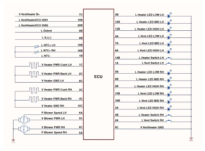
Schematic diagrams
| Circuit Diagram |
Repair procedures
| Removal |
Seat Ventilation Unit
| 1. |
Disconnect the negative (-) battery terminal. |
| 2. |
Remove the front seat assembly [RH]. (Refer to Body - "Front Seat Assembly") |
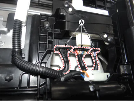
| 3. |
Disconnect the seat ventilation unit connectors (A).
|
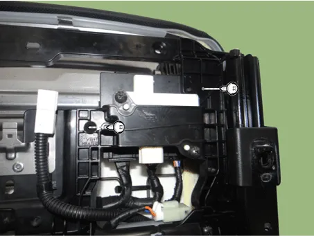
| 4. |
Remove the seat ventilation unit (A) after loosening the mounting screws.
|
Seat Ventilation Blower
| 1. |
Disconnect the negative (-) battery terminal. |
| 2. |
Remove the front seat assembly [LH/RH]. (Refer to Body - "Front Seat Assembly") |
| 3. |
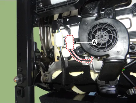
Disconnect the seat ventilation blower connector (A).
|
| 4. |
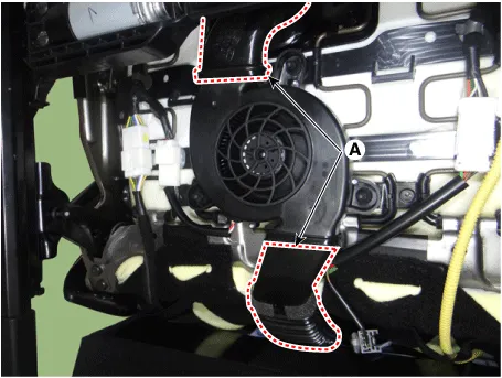
Remove the seat ventilation blower ducts (A).
|
| 5. |
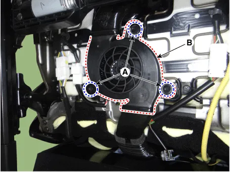
Remove the seat ventilation blower (B) after removing the mounting packing (A).
|
| Installation |
Seat Ventilation Unit
| 1. |
Install the seat ventilation unit after connecting the connector. |
| 2. |
Install the front seat assembly [RH]. |
| 3. |
Connect the negative (-) battery terminal. |
Seat Ventilation Blower
| 1. |
Install the seat ventilation blower. |
| 2. |
Install the seat ventilation blower ducts. |
| 3. |
Connect the seat ventilation blower connector. |
| 4. |
Install the front seat assembly [LH/RH]. |
| 5. |
Connect the negative (-) battery terminal. |


Other information:
Kia Stinger (CK) 2018-2023 Service Manual: AGM Battery
Specifications Specification ▷CMF90L-DIN Item Specification Model type CMF90L-DIN Capacity [20HR/5HR] (AH) 90/72 Cold Cranking Amperage (A) 740 (SAE) / 740 (EN) Reserve Capacity (Min) 170 ▷MF90L-DIN : Operable Item Specification Model type MF90L-DINKia Stinger (CK) 2018-2023 Service Manual: Air Conditioner Refrigerant/Compressor
Repair procedures Refrigerant Recovery When removing HFC-134a (R-134a) from the air conditioning system, use only U.L.-listed service equipment certified to meet the requirements of SAE J2210. • Air conditioning refrigerant or lubricant vapor can irritate your eyes, nose, or throat.Categories
- Manuals Home
- Kia Stinger Owners Manual
- Kia Stinger Service Manual
- New on site
- Most important about car
