Kia Stinger CK: Seat Electrical / Seat Heater Switch
Components and components location
| Components |
| Front Seat Switch |
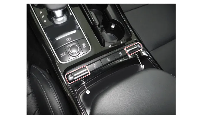
| 1. Driver side seat heater switch
|
2. Passenger side seat heater
switch |
| Rear Seat Switch |
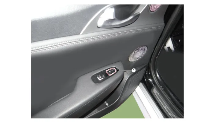
| 1. Rear seat heater switch (LH/RH)
|
Description and operation
| Description |
Heater Seat Smart Control Technology
| • |
To prevent low temperature burn, seat heater temperature will automatically be lowered after a certain period of time. (Low temperature burn condition: Over 30 minutes at 50°C) |
Heater Seat Smart Control Operation
[1st Row Seat]
| • |
Change to "MID" after 30 minutes in "HIGH", then "LOW" after 60 minutes in "MID" |
| • |
Change to "LOW" after 60 minutes in "MID" |
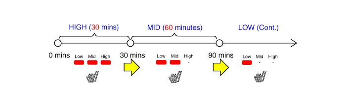
[2nd Row Seat]
| • |
Change to "MID" after 30 minutes in "HIGH", then "LOW" after 60 minutes in "MID" |
| • |
Change to "LOW" after 60 minutes in "MID" |
|

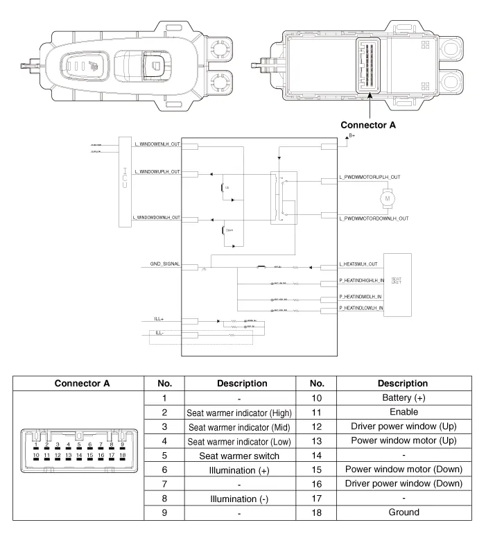
Schematic diagrams
| Circuit Diagram |
Front Seat Heater Swtich

Rear Seat Heater Swtich
Repair procedures
| Removal |
Put on gloves to protect your hands. |

|

Front Seat Heater Swtich
| 1. |
Disconnect the negative (-) battery terminal. |
| 2. |
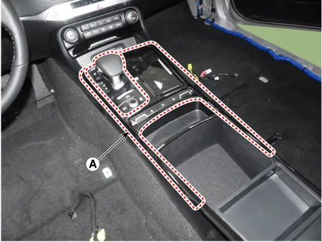
Remvoe the console upper complete (A) by using a remover.
|
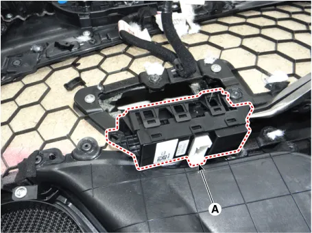
| 3. |
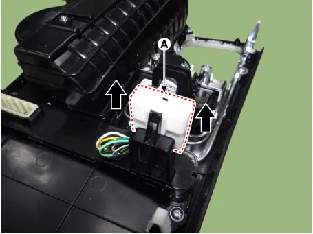
Disconnect the connectors (A) from the console upper complete.
|

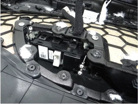
| 4. |
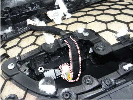
Remove the connector (A) from the console floor switch complete.
|
| 5. |
Remove the console floor switch complete (A) after loosening the mounting screws.
|

Rear Seat Heater Swtich
| 1. |
Disconnect the negative (-) battery terminal. |
| 2. |
Remove the rear door trim. (Refer to Body - "Rear Door Trim") |
| 3. |
Disconnect the power window switch connector (A).
|
| 4. |
Remove the power window switch (A) after loosening the mounting screws.
|
| Installation |
Front Seat Heater Swtich
| 1. |
Install the console floor switch complete. |
| 2. |
Install the connector from the console floor switch complete. |
| 3. |
Connect the connectors from the console upper complete. |
| 4. |
Install the console upper complete. |
| 5. |
Connect the negative (-) battery terminal. |
Rear Seat Heater Swtich
| 1. |
Install the power window switch. |
| 2. |
Connect the power window switch connector. |
| 3. |
Install the rear door trim after connecting the connector. |
| 4. |
Connect the negative (-) battery terminal. |


Other information:
Kia Stinger (CK) 2018-2023 Service Manual: Maintenance services
You should exercise the utmost care to prevent damage to your vehicle and injury to yourself whenever performing any maintenance or inspection procedures. Should you have any doubts concerning the inspection or servicing of your vehicle, we strongly recommend that you have an authorized Kia dealer perform this work. An authorized Kia dealer has factorytrained technicians and genuine Kia parts to service your vehicle properly.Kia Stinger (CK) 2018-2023 Service Manual: Engine Room Under Cover
Repair procedures Removal and Installation Engine Room Front Under Cover. 1. Remove the engine room front under cover (A). Tightening torque : 7.8 - 11.8 N·m (0.8 - 1.2 kgf·m, 5.8 - 8.7 lb·ft) 2. Install in the reverse order of removal. Engine Room Rear Under Cover.Categories
- Manuals Home
- Kia Stinger Owners Manual
- Kia Stinger Service Manual
- New on site
- Most important about car
