Kia Stinger CK: Wireless Power Charger (WPC) System / Wireless Power Charging (WPC) Unit
Components and positions
| Components |
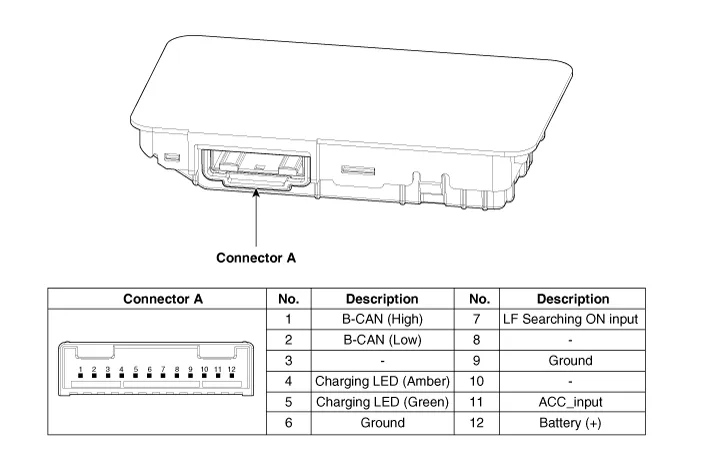
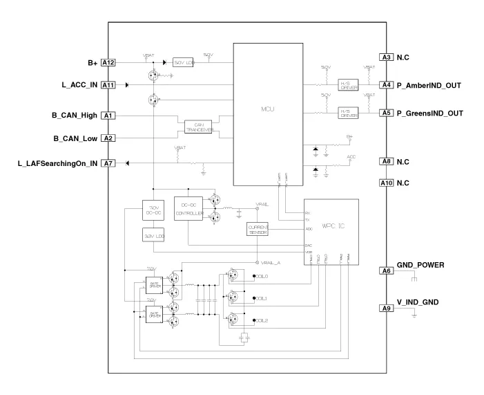
Circuit diagram
| Circuit Diagram |
Repair procedures
| Removal |
|

|

| 1. |
Disconnect the negative (-) battery terminal. |
| 2. |
Remove the console complete assembly. (Refer to Body - "Floor Console Assembly") |
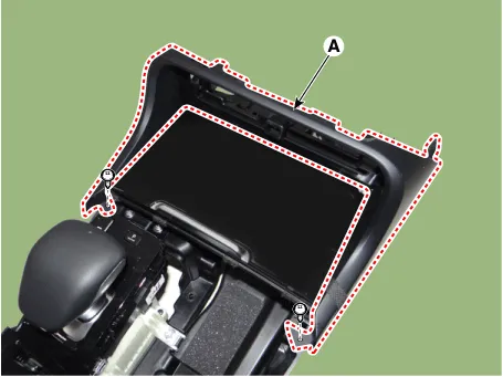
| 3. |
Remove the front cover (A) after loosening the mounting screws.
|
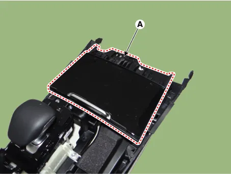
| 4. |
Remove the floor console tray (A) by using a remover.
|
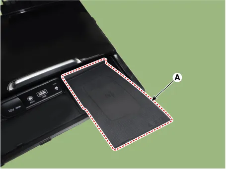
| 5. |
Remove the wireless charging pad (A).
|
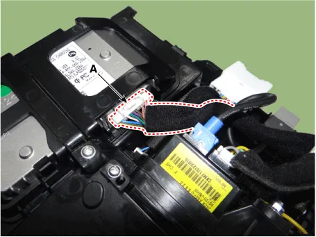
| 6. |
Disconnect the wireless power charging unit connector (A).
|
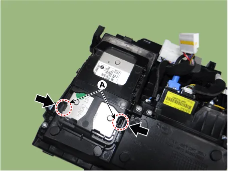
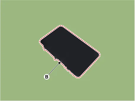
| 7. |
Remove the wireless power charging unit (B) by pressing the fixing hooks (A).
|
| Installation |
| 1. |
Install the wireless power charging unit. |
| 2. |
Connect the wireless power charging unit connector. |
| 3. |
Install the wireless charging pad. |
| 4. |
Install the floor console tray. |
| 5. |
Install the front cover. |
| 6. |
Install the console complete assembly. |
| 7. |
Connect the negative (-) battery terminal. |
| [Diagnosis With KDS] |
| 1. |
The body electrical system can be more quickly diagnosed for troubles by using the vehicle diagnostic system (KDS). KDS provides the following information.
|
| 2. |
To diagnose the vehicle by using the diagnostic equipment, select "vehicle model" and "wireless power charger system" to be inspected. |
| 3. |
To inquire the current status of input/output values, select the "Sensor Data" menu The input/output values of the sensors corresponding to the selected module can be checked. |
| 4. |
To perform forced operation of the selected module input, select "Actuation Test". |
| 5. |
To inquire the cause of trouble for each module by self diagnosis, select 'Diagnostic Trouble Code'. |


Other information:
Kia Stinger (CK) 2018-2023 Service Manual: Rear Suspension System
Components and components location Components Location 1. Rear upper arm rear 2. Rear upper arm front 3. Rear cross member 4. Rear differential 5. Rear stabilizer bar 6. Rear shock absorber 7. Rear axle 8. Rear assist arm 9. Rear lower armKia Stinger (CK) 2018-2023 Service Manual: Headlamp Leveling System
Components and components location Component Location 1. Headlamp leveling unit (Auto) 2. Headlamp leveling actuator (Built in leveling actuator) 3. Headlamp leveling switch (Manual)Categories
- Manuals Home
- Kia Stinger Owners Manual
- Kia Stinger Service Manual
- New on site
- Most important about car
