Kia Stinger CK: Windshield Wiper/Washer / Wireless Power Charger (WPC) System
Contents:
Specification
| Specifications |
|
Item |
Specification |
|
Rated voltage |
DC 12 V |
|
Operating voltage |
DC 9.0 - 16.0 |
|
Operating temperature |
-86 - 167°F (-30 - 75°C) |
|
Dark current |
Max. 1 mA |
|
Output power |
5 W |
|
Output frequency |
110 ± 5 kHz |
Components and positions
| Components |

| 1. Integrated body control unit
(IBU) 2. Wireless power charging unit |
3. Instrument cluster |
Description and operating principle
| Description and Operation |
Wireless Power Charger System
During ACC or IG ON, battery voltage is supplied to the wireless power charger system to transmit an output of 5 W to mobile phone.
Mobile phones certified with the wireless charging standard WPC (Qi 1.2.2) or equipped with an exclusive wireless charging case can be used.
Wireless Power Charging System Flow Chart
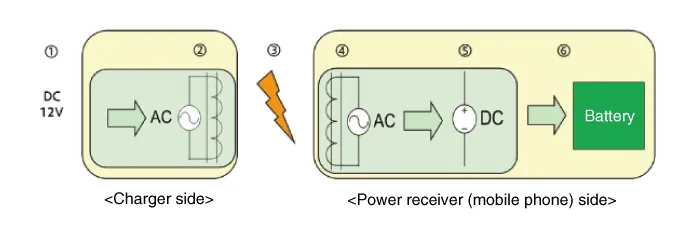
| 1. |
Supply vehicle power. |
| 2. |
Convert to AC. Generate electromagnetic field in 1st coil. |
| 3. |
Generate induced current in power receiver from electromagnetic induction. |
| 4. |
Generate AC in 2nd coil. |
| 5. |
Convert to DC. |
| 6. |
Charge battery. |
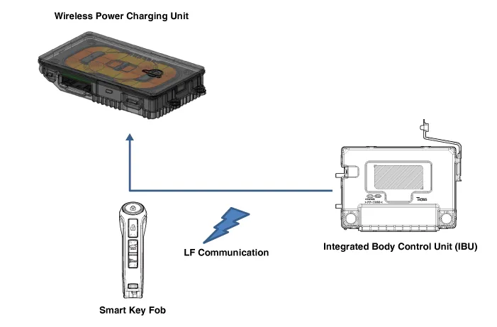
System Configuration Diagram
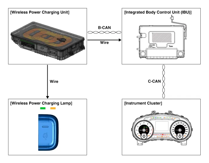
| 1. |
Instrument cluster : Alerts about contact with mobile phone. |
| 2. |
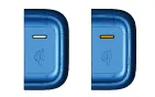
Wireless charging lamp : Displays the charging status. |
| 3. |
Integrated body control unit (IBU) :
|
Major Functions of Wireless Power Charger System
| 1. |
Charging Function
|
||||||||||||||||||||||||||||||||


| 2. |
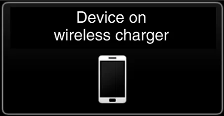
If you leave the smart phone on the charging pad when the vehicle ignition is in OFF, the vehicle will alert you through warning messages.
|
| 3. |
Overheating prevention
|

| 4. |
Foreign matter detection
|

| 5. |
IBU unit LF frequency interference prevention This function prevents interference between the wireless charging frequency and smart key unit frequency band.
|
| 6. |
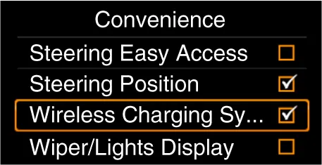
Turn the wireless charging function ON/OFF with USM.
※ Tailgate applies to RV vehicle models. |
Protection of Wireless Power Charger System
|
Item |
Condition |
Status |
|
Protects against low/high voltage |
Protects and stops charging under 8.5 V and over 16.5 V |
LED OFF (Stops operation) |
|
Charges over 9.0 V and under 16.0 V |
||
|
Protects against reverse voltage |
Protects and stops charging in case of reverse voltage |
LED OFF (Stops operation) |
|
Protects against overcurrent |
Protects and stops charging in case of detecting 4.5 A |
Amber LED blinks |
|
Protects against overheating |
Protects and stops charging in case of detecting 158°F (70°C) by internal
temperature sensor of wireless charging module |
Amber LED blinks |
|
Resumes under 149°F (65°C) |
||
|
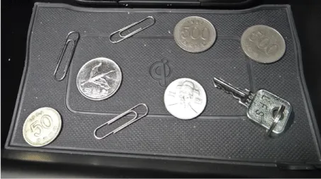
Foreign matter (Coins, clips, precious metals, etc.) |
Protects and stops charging in case of detecting foreign matter (overheating
prevention) |
Amber LED blinks |
|
Prevents frequency interference |
Protects and stops charging by activating SMK in case door or tailgate is
open |
LED OFF (Stops operation) |
|
Resumes in 3.5 seconds after all doors and tailgate are closed and SMK operation
is completed |
||
|
Alert for contact with mobile phone |
In case of smart phone on the charging pad when opening the door after ignition
OFF |
Displays warning message on the instrument panel (for about 4-5 seconds)
|
※ Tailgate applies to RV vehicle models.
Wireless Power Charging (WPC) Unit ➤
Wireless Power Charging (WPC) Lamp ➤


Other information:
Kia Stinger (CK) 2018-2023 Service Manual: Drive Belt Tensioner
Repair procedures Removal and Installation 1. Remove the drive belt. (Refer to Drive Belt System - "Drive Belt") 2. Remove the drive belt auto tensioner pulley (A). Tightening torque : 53.9 - 63.7 N·m (5.5 - 6.5 kg·m, 39.8 - 47.0 lb·ft) Tensioner pulley bolt is left-hands screw.Kia Stinger (CK) 2018-2023 Service Manual: ESP Control Module
Components and components location Components 1. FR 2. RL 3. RR 4. FL 5. MC2 (SEC) 6. MC1 (PRI) 7. Damper 8. ESP control module connector 9. ESP control module bracket Repair procedures Removal [LHD] 1. Turn ignition switch OFF and disconnect the negative (-) battery cable.Categories
- Manuals Home
- Kia Stinger Owners Manual
- Kia Stinger Service Manual
- New on site
- Most important about car
Contents
