Kia Stinger CK: Specifications & Consumer information / Recommended lubricants and capacities
To help achieve proper engine and powertrain performance and durability, use only lubricants of the proper quality. The correct lubricants also help promote engine efficiency that results in improved fuel economy.
These lubricants and fluids are recommended for use in your vehicle.
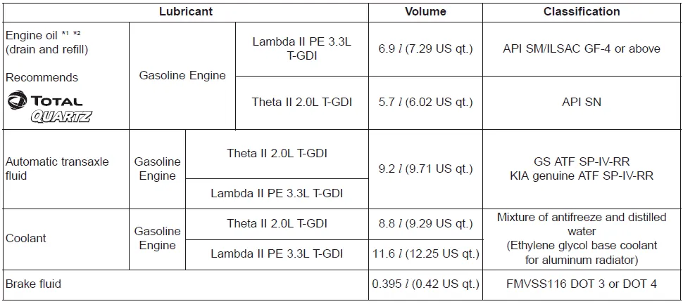
*1 : Refer to the recommended SAE viscosity numbers on the next page.
*2 : Engine oils labeled Energy Conserving Oil are now available. Along with other
additional benefits, they contribute to fuel economy by reducing the amount of fuel
necessary to overcome engine friction. Often, these improvements are difficult to
measure in everyday driving, but in a year’s time, they can offer significant cost
and energy savings.
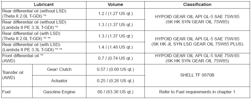
*3 : Regardless of oil change intervals, replace oil immediately if Rear-Differential
or Front-Differential is submerged.
*4 : Be sure to inject oil for exclusive use of LSD when replacing Rear Differential
(for LSD) Oil.
Recommended SAE viscosity number
Engine oil viscosity (thickness) has an effect on fuel economy and cold weather operating (engine start and engine oil flowability). Lower viscosity engine oils can provide better fuel economy and cold weather performance; however, higher viscosity engine oils are required for satisfactory lubrication in hot weather. Using oils of any viscosity other than those recommended could result in engine damage. When choosing an oil, consider the range of temperature your vehicle will be operated in before the next oil change. Proceed to select the recommended oil viscosity from the chart.
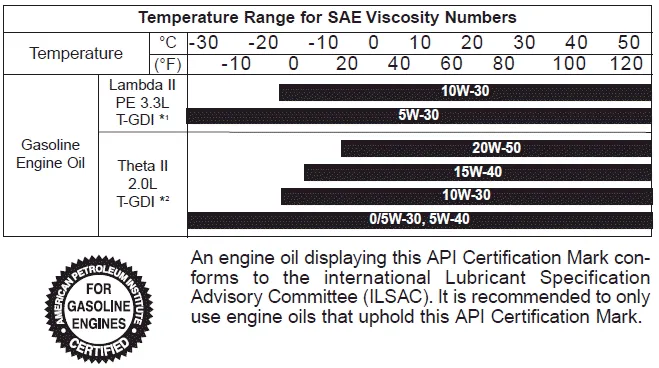
*1 : For better fuel economy, it is recommended to use the engine oil of a viscosity
grade SAE 5W 30 (API SM/ILSAC GF-4 or above). However, if the engine oil is not
available in your country, select the proper engine oil using the engine oil viscosity
chart.
*2 : For better fuel economy, it is recommended to use the engine oil of a viscosity
grade SAE 0W 30 (API SN or above). However, if the engine oil is not available in
your country, select the proper engine oil using the engine oil viscosity chart.


Other information:
Kia Stinger (CK) 2018-2023 Owner's Manual: Rear Oil Seal
Repair procedures Replacement 1. Remove the automatic transmission. (Refer to Automatic Transmission System - "Automatic Transmission") 2. Remove the drive plate. (Refer to Cylinder Block - "Drive Plate") 3. Remove the rear oil seal (A). 4.Kia Stinger (CK) 2018-2023 Owner's Manual: Tire (pressure & tread wear)
Repair procedures Inspection 1. Check the tire pressure. 17(inch) : 245 + 7.0 kPa (36 + 1 psi) 18(inch) : 245 + 7.0 kPa (36 + 1 psi) 19(inch) : 245 + 7.0 kPa (36 + 1 psi) Tire Rotation Checking For Pull And Wander If the steering pulls to one side, rotate the tires according to the following wheel rotation procedure.Categories
- Manuals Home
- Kia Stinger Owners Manual
- Kia Stinger Service Manual
- New on site
- Most important about car
