Kia Stinger CK: Transfer Assembly / Transfer Case Assembly
Components and components location
| Components Location |

| 1. Engine
2. Transmission 3. Rear differential 4. Rear propeller shaft |
5. Transfer
case 6. Front propeller shaft 7. Front differential |
Repair procedures
| Removal |
In case of replacing the controller (ECU) and transfer case due to changing characteristics of the frictional materials inside the transfer case, it is necessary to check and enter the calibration data.
|

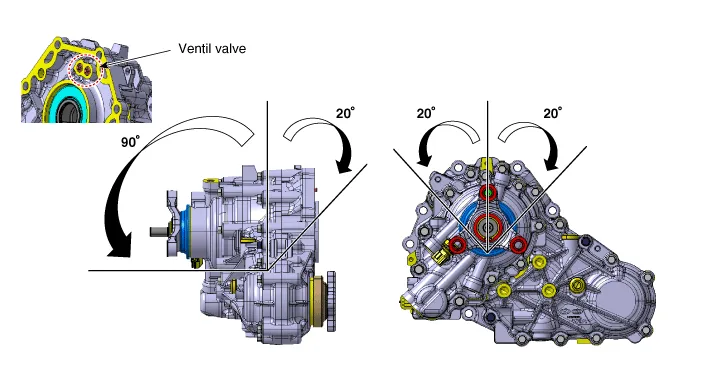
Cautions in handling the transfer case A. Preventing the oil leaking
|
| 1. |
Turn ignition switch OFF and disconnect the negative (-) battery cable. |
| 2. |
Remove the under cover. D 2.2 R VGT (Refer to Engine Mechanical System - "Engine Room Under cover") G 2.0 T-GDI THETA II (Refer to Engine Mechanical System - "Engine Room Under cover") G 3.3 T-GDI LAMBDA II (Refer to Engine Mechanical System - "Engine Room Under cover") |
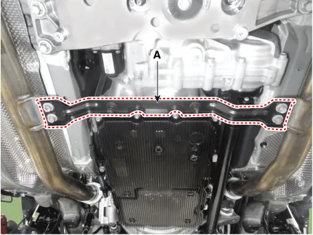
| 3. |
Remove the front muffler stay (A).
|
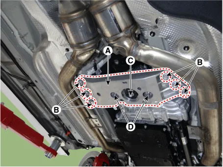
| 4. |
Remove the transmission cross member (A).
|
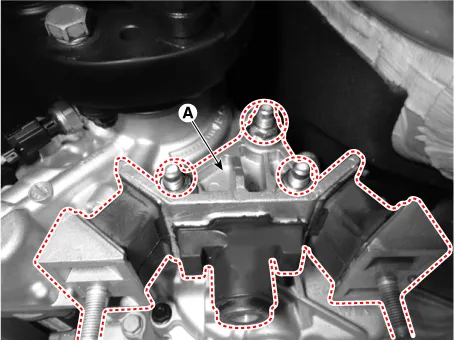
| 5. |
Remove the transmission cross member bracket (A).
|
| 6. |
Remove the propeller shaft. (Refer to Driveshaft and axle - "Propeller Shaft Assembly") |
| 7. |
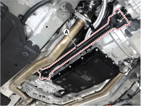
Remove the front propeller shaft (A).
|
| 8. |
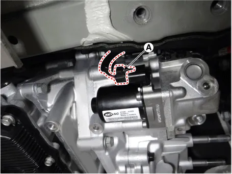
Disconnect the transfer actuator connector (A).
|
| 9. |
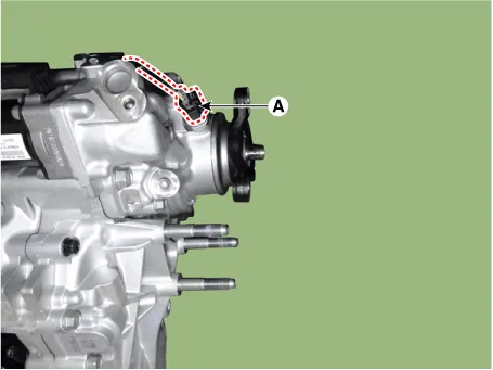
Disconnect the pressure sensor connector (A).
|
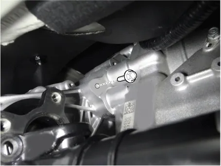
| 10. |
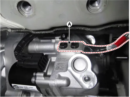
Loosen the bolts and then bracket (A).
|
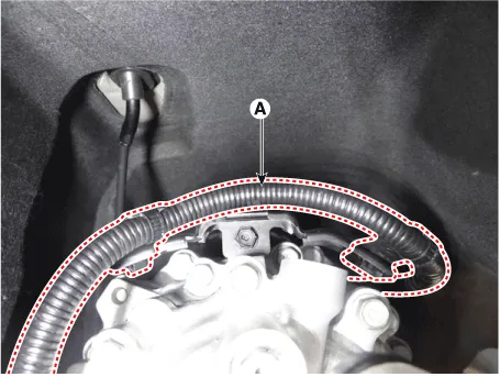
| 11. |
Remove the transfer wire ring (A).
|
| 12. |
Loosen the transfer bolts and then remove the transfer (A).
|

| Installation |
| 1. |
Install in the reverse order of removal.
|


Other information:
Kia Stinger (CK) 2018-2023 Service Manual: LCD Modes
(1) SPORT mode (if equipped) This mode displays Gauge, Lap Timer, G-Force. (2) Trip Computer mode This mode displays driving information such as the tripmeter, fuel economy, and so on. ❈ For more details, refer to “Trip Computer” in this chapter. (3) Turn by Turn mode (if equipped) This mode displays the state of the navigation. (4) LKA/SCC mode (if equipped) This mode displays the state of the Smart Cruise Control (SCC) and Lane keeping Assist (LKA).Kia Stinger (CK) 2018-2023 Service Manual: A/C Pressure Transducer
Description and operation Description A/C pressure transducer measures the pressure in high pressure line and converts it into voltage. Based on the converted voltage, engine ECU controls cooling fan by operating it at high or low speed. Engine ECU stops the operation of compressor when the temperature of refrigerant line is too high or low irregularly to optimize air conditioning system.Categories
- Manuals Home
- Kia Stinger Owners Manual
- Kia Stinger Service Manual
- New on site
- Most important about car
