Kia Stinger CK: Engine Control / Fuel System / Specifications
Service data
| Service Data |
| Fuel Delivery System |
|
Items |
Specification |
|
|
Fuel Tank |
Capacity |
60 L (15.8 U.S.gal., 63.4 U.S.qt., 52.7 Imp.qt.) |
|
Fuel Filter |
Type |
Paper type |
|
Fuel Pressure |
Low Pressure Fuel Line |
Over 290 kPa (Over 2.9 bar, Over 2.95 kgf/cm², Over 42.06 psi) |
|
High Pressure Fuel Line |
2.0 - 20 MPa (20.4 - 203 kgf/cm², 290.1 - 2900 psi) |
|
|
Fuel Pump |
Type |
Electrical, in-tank type |
|
Driven by |
Electric motor |
|
|
High Pressure Fuel Pump |
Type |
Mechanical type |
|
Driven by |
Camshaft |
|
| Fuel pump motor |
|
Item |
Specification |
||
|
Output Voltage (V) |
12.6 |
||
|
Low Pressure Fuel Line |
bar |
3.5 - 6.0 |
|
|
kPa |
350 - 600 |
||
|
kgf/cm² |
3.5 - 6.1 |
||
|
psi |
50.7 - 87.0 |
||
| Fuel sender |
[Main Fuel Sender]
|
Position |
Resistance (Ω) |
Capacity (ℓ) |
|
E |
148 - 152 |
4.5 |
| 1/2
|
6.5 - 8.5 |
31.2 |
|
F |
6.5 - 8.5 |
58.5 |
[Sub Fuel Sender]
|
Position |
Resistance (Ω) |
Capacity (ℓ) |
|
E |
148 - 152 |
4.5 |
| 1/2
|
148 - 152 |
31.2 |
|
F |
6.5 - 8.5 |
58.5 |
[Main Fuel Sender + Sub Fuel Sender Composite resistance]
|
Position |
Resistance (Ω) |
Capacity (ℓ) |
|
E |
296 - 304 |
4.5 |
| 1/2
|
154.5 - 160.5 |
31.2 |
|
F |
13 - 17 |
58.5 |
| Sensors |
Manifold Absolute Pressure Sensor (MAPS)
▷ Type: Piezo-resistive pressure sensor type
▷ Specification
|
Item |
Specification |
|
Output Voltage (V) |
5 |
|
Pressure (KPa) |
32.5 - 284 |
|
Operating Voltage (V) |
4.5 - 5.5 |
|
Pressure [kPa (kgf/cm², psi)] |
Output Voltage (Vref = 5V) |
|
32.5 (0.33, 4.71) |
0.5 |
|
70 (0.71, 10.1) |
1.1 |
|
270 (2.75, 39.1) |
4.3 |
|
284 (2.89, 41.1) |
4.5 |
Boost Pressure Sensor (BPS)
▷ Type: Piezo-resistive pressure sensor type
▷ Specification
|
Item |
Specification |
|
Output Voltage (V) |
5 |
|
Pressure (KPa) |
32.5 - 284 |
|
Operating Voltage (V) |
4.5 - 5.5 |
|
Pressure [kPa (kgf/cm², psi)] |
Output Voltage (Vref = 5V) |
|
32.5 (0.33, 4.71) |
0.5 |
|
70 (0.71, 10.1) |
1.1 |
|
270 (2.75, 39.1) |
4.3 |
|
284 (2.89, 41.1) |
4.5 |
Intake Air Temperature Sensor (IATS)
▷ Type: Thermistor type
▷ Specification
|
Temperature |
Resistance (kΩ) |
|
|
°C |
°F |
|
|
-40 |
-40 |
40.93 - 48.35 |
|
-20 |
-4 |
13.89 - 16.03 |
|
0 |
32 |
5.38 - 6.09 |
|
10 |
50 |
3.48 - 3.90 |
|
20 |
68 |
2.31 - 2.57 |
|
40 |
104 |
1.08 - 1.21 |
|
50 |
122 |
1.56 - 1.74 |
|
60 |
7140 |
0.54 - 0.62 |
|
80 |
176 |
0.29 - 0.34 |
Ambient Temperature Sensor (ATS)
▷ Specification
|
Temperature[⁰C(⁰F)] |
Resistance(kΩ) |
|
-40(-40) |
811.1 - 956.8 |
|
-20(-4) |
255.6 - 287.7 |
|
0(32) |
91.5 - 98.8 |
|
20(68) |
36.6 - 38.0 |
|
30(86) |
23.8 - 24.7 |
|
40(104) |
15.7 - 16.6 |
|
50(122) |
10.6 - 11.3 |
|
60(140) |
7.2 - 7.9 |
|
80(176) |
3.6 - 4.0 |
Engine Coolant Temperature Sensor (ECTS)
▷ Type: Thermistor type
▷ Specification
|
Temperature |
Resistance (kΩ) |
|
|
°C |
°F |
|
|
-40 |
-40 |
48.14 |
|
-20 |
-4 |
14.13 - 16.83 |
|
0 |
32 |
5.79 |
|
20 |
68 |
2.31 - 2.59 |
|
40 |
104 |
1.15 |
|
60 |
140 |
0.59 |
|
80 |
176 |
0.32 |
Throttle Position Sensor (TPS) [integrated into ETC Module]
▷ Type: Variable resistor type
▷ Specification
|
Throttle Angle(°) |
Output Voltage (V) [Vref = 5V] |
|
|
TPS1 |
TPS2 |
|
|
0 |
0 |
5.0 |
|
10 |
0.48 |
4.52 |
|
20 |
0.95 |
4.05 |
|
30 |
1.43 |
3.57 |
|
40 |
1.90 |
3.10 |
|
50 |
2.38 |
2.62 |
|
60 |
2.86 |
2.14 |
|
70 |
3.33 |
1.67 |
|
80 |
3.81 |
1.19 |
|
90 |
4.29 |
0.71 |
|
100 |
4.76 |
0.24 |
|
105 |
5.0 |
0 |
|
C.T (6-15°) |
0.29 - 0.71 |
4.29 - 4.71 |
|
W.O.T (93-102°) |
4.43 - 4.86 |
0.14 - 0.57 |
Crankshaft Position Sensor (CKPS)
▷ Type: Hall effect type
|
Item |
Specification |
|
Type |
Magnetic field sensitive |
|
Output Voltage (V) |
4.75 - 5.25 (25°C) |
|
Input Voltage (V) |
0.6 - 4.5 |
|
Air Cap (mm) |
0.5 - 1.5 |
Camshaft Position Sensor (CMPS)
▷ Type: Hall effect type
|
Item |
Specification |
|
Air Cap (mm) |
0.2 - 2.0 |
Knock Sensor (KS)
▷ Type: Piezo-electric type
▷ Specification
|
Item |
Specification |
|
Capacitance (pF) |
850 - 1,150 |
|
Resistance (MΩ) |
Approx. 1 |
Heated Oxygen Sensor (HO2S) [Bank 1/Sensor 1]
▷ Type: Zirconia (ZrO2) [Linear] Type
▷ Specification
|
Item |
Specification |
|
Heater Resistance (Ω) |
2.5 - 4.0 [20°C(69.8°F)] |
Heated Oxygen Sensor (HO2S) [Bank 1/Sensor 2]
▷ Type: Zirconia (ZrO2) [Binary] Type
▷ Specification
|
Item |
Specification |
|
Heater Resistance (Ω) |
3.3 - 4.1 [20°C(69.8°F)] |
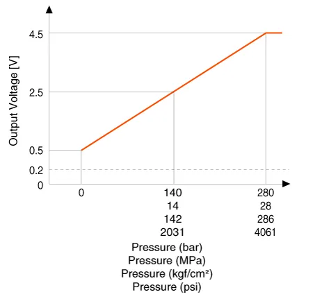
Rail Pressure Sensor (RPS)
▷ Type: Piezo-electric type
▷ Specification
|
Pressure |
Output Voltage (V) [Vref=5V] |
|
|
bar |
[MPa (kgf/cm², psi)] |
|
|
0 |
0 (0, 0) |
0.5 |
|
140 |
14 (142, 2031) |
2.5 |
|
280 |
28 (286, 4061) |
4.5 |
CVVT Oil Temperature Sensor (OTS)
▷ Type: Thermistor type
▷ Specification
|
Temperature [°C (°F)] |
Resistance (kΩ) |
|
-40 |
52.15 |
|
-20 |
28.82 |
|
0 |
14.08 - 19.45 |
|
20 |
2.16 - 2.78 |
|
40 |
1.11 |
|
60 |
0.54 |
|
80 |
0.26 - 0.32 |
|
100 |
0.16 |
|
120 |
0.1 |
|
140 |
0.06 |
Accelerator Position Sensor (APS)
▷ Type: Variable resistor type
▷ Specification
|
Accelerator Position |
Output Voltage (V) [Vref = 5V] |
|
|
APS1 |
APS2 |
|
|
C.T |
0.7 - 0.8 |
0.33 - 0.43 |
|
W.O.T |
3.99 - 4.23 |
1.94 - 2.18 |
| Actuators |
ETC Motor [integrated into ETC Module]
▷ Specification
|
Item |
Specification |
|
Coil Resistance (Ω) |
1.1 - 1.7 [20°C(68°F)] |
Injector
▷ Specification
|
Item |
Specification |
|
Coil Resistance (Ω) |
1.4 - 1.6 [20°C(68°F)] |
Purge Control Solenoid Valve (PCSV)
▷ Specification
|
Item |
Specification |
|
Coil Resistance (Ω) |
18.5 - 22.5 [20°C(68°F)] |
CVVT Oil Control Valve (OCV) [Bank 1 / Exhaust]
▷ Specification
|
Item |
Specification |
|
Coil Resistance (Ω) |
6.9 - 7.9 [20°C(68°F)] |
Fuel Pressure Control Valve (FPCV)
▷ Specification
|
Item |
Specification |
|
Coil Resistance (Ω) |
0.47 - 0.53 [20°C(68°F)] |
RCV Control Solenoid Valve
▷ Specification
|
Item |
Specification |
|
Coil Resistance (Ω) |
28.3 - 31.1 [20°C(68°F)] |
Variable Charge Motion Actuator (VCMA)
▷ Specification
|
Item |
Specification |
|
Coil Resistance (Ω) |
18.5 - 22.5 [20°C(68°F)] |
E-CVVT Motor [Bank 1 / Intake]
▷ Specification
|
Item |
Specification |
|
Operation angle |
90° |
|
Initial postion |
Completely Advance (When starting, it can be adjusted) |
|
Gear ratio |
60:01:00 |
|
Motor Max. power |
140W / 12V |
|
Current |
Max. 35A [-30 °C] / 1A [When maintaining the phase] |
| Fuel Delivery System Item |
Fuel Pump Motor
▷ Specification
|
Item |
Specification |
|
Normal state |
Operate |
Fuel sender
▷ Specification
|
Position |
Resistance (Ω) |
|
E |
297 - 303 |
| 1/2
|
80 - 84 |
|
F |
14 - 16 |
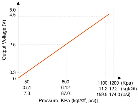
Fuel Pressure Sensor (FPS)
▷ Specification
|
Pressure [KPa (kgf/cm², psi)] |
Output Voltage (V) [Vref = 5V] |
|
50 (0.51, 7.3) |
0.3 |
|
600 (6.12, 87.0) |
2.5 |
|
1100 (11.2, 159.5) |
4.5 |
| Service Standard |
|
Item |
Specification |
||
|
Ignition Timing (°) |
BTDC 6 ± 10 |
||
|
Idle Speed (rpm) |
A/C OFF |
Neutral, N, P-range |
640 ± 100 |
|
D-range |
600 ± 100 |
||
|
A/C ON |
Neutral, N, P-range |
660 ± 100 |
|
|
D-range |
660 ± 100 |
||
Tightening torque
| Tightening Torques |
Engine Control System
|
Item |
kgf·m |
N·m |
lb·ft |
|
ECM bracket mounting bolt/ nut |
1.0 - 1.2 |
9.8 - 11.8 |
7.2 - 8.7 |
|
Electronic Throttle Control (ETC) Module mounting bolt |
1.0 - 1.2 |
9.8 - 11.8 |
7.2 - 8.7 |
|
Manifold Absolute Pressure Sensor (MAPS) mounting bolt |
1.0 - 1.2 |
9.8 - 11.8 |
7.2 - 8.7 |
|
Intake Air Temperature Sensor (IATS) mounting bolt |
1.0 - 1.2 |
9.8 - 11.8 |
7.2 - 8.7 |
|
Boost Pressure Sensor (BPS) mounting bolt |
1.0 - 1.2 |
9.8 - 11.8 |
7.2 - 8.7 |
|
Crankshaft position sensor (CKPS) mounting bolt |
1.0 - 1.2 |
9.8 - 11.8 |
7.2 - 8.7 |
|
Camshaft position sensor (CMPS) [Bank 1 / Intake] mounting bolt |
1.0 - 1.2 |
9.8 - 11.8 |
7.2 - 8.7 |
|
Camshaft position sensor (CMPS) [Bank 1 / Exhaust] mounting bolt |
1.0 - 1.2 |
9.8 - 11.8 |
7.2 - 8.7 |
|
Knock Sensor (KS) mounting bolt |
1.9 - 2.4 |
18.6 - 23.5 |
13.7 - 17.4 |
|
Heated oxygen sensor (HO2S) [Bank 1 / sensor 1] |
4.0 - 5.0 |
39.2 - 49.1 |
28.9 - 36.2 |
|
Heated oxygen sensor (HO2S) [Bank 1 / sensor 2] |
4.0 - 5.0 |
39.2 - 49.1 |
28.9 - 36.2 |
|
Rail Pressure Sensor (RPS) |
1.8 - 2.2 |
18.0 - 22.0 |
13.3 - 16.2 |
|
Accelerator pedal module mounting bolt/nut |
0.9 - 1.4 |
8.8 - 13.7 |
6.5 - 10.1 |
|
CVVT Oil Control Valve (OCV) [Bank 1 / Exhaust] mounting bolt |
1.0 - 1.2 |
9.8 - 11.8 |
7.2 - 8.7 |
|
Variable Charge Motion Actuator (VCMA) mounting bolt |
1.0 - 1.4 |
9.8 - 11.8 |
7.2 - 8.7 |
|
Oil Temperature Sensor (OTS) |
3.5 - 4.5 |
34.3 -44.1 |
25.3 - 32.5 |
|
RCV Control Solenoid Valve |
1.0 - 1.2 |
9.8 - 11.8 |
7.2 - 8.7 |
Fuel Delivery System
|
Item |
kgf·m |
N·m |
lb·ft |
|
Fuel tank band mounting nut |
4.0 - 5.5 |
39.2 - 54.0 |
28.9 - 39.8 |
|
High pressure fuel pipe mounting nut |
2.7 - 3.3 |
26.5 - 32.4 |
19.5 - 23.9 |
|
High pressure fuel pipe function block mounting bolt |
0.8 - 1.2 |
7.8 - 11.8 |
5.8 - 8.7 |
|
Filler-neck assembly bracket mounting bolt |
0.4 - 0.6 |
3.9 - 5.9 |
2.9 - 4.3 |
|
Delivery pipe mounting bolt |
1.9 - 2.4 |
18.6 - 23.5 |
13.7 - 17.4 |
|
High pressure fuel pump mounting bolt |
1.3 - 1.5 |
12.8 - 14.7 |
9.4 - 10.9 |


Other information:
Components and components location Components 1. Master cylinder 2. Brake booster 3. Brake reservoir Repair procedures Removal [LHD] 1. Turn ignition switch OFF and disconnect the negative (-) battery cable. 2. Remove the brake fluid from the master cylinder reservoir with a syringe.Opening the hood 1. Pull the release lever to unlatch the hood. The hood should pop open slightly. Only open the hood with the vehicle on a flat surface, engine is turned off, shift lever placed in P (Park) position and setting the parking brake. 2. Go to the front of the vehicle, raise the hood slightly, push the secondary latch (1) left side of the hood center and lift the hood (2).Categories
- Manuals Home
- Kia Stinger Owners Manual
- Kia Stinger Service Manual
- New on site
- Most important about car
