Kia Stinger CK: Engine Control System / Exhaust Gas Temperature Sensor (EGTS)
Specifications
| Specification |
Exhaust Gas Temperature Sensor (EGTS) #1, 2
▷ Type : Thermistor type
|
Temperature [°C (°F)] |
Resistance (kΩ) |
|
-40 (-40) |
0.17 |
|
0 (-32) |
0.201 |
|
100 (212) |
0.276 |
|
200 (392) |
0.35 |
|
300 (572) |
0.42 |
|
400 (752) |
0.489 |
|
500 (932) |
0.555 |
|
600 (1112) |
0.618 |
|
700 (1292) |
0.68 |
|
800 (1472) |
0.739 |
|
850 (1562) |
0.767 |
Description and operation
| Description |
Installed in exhaust manifold, the Exhaust Gas Temperature Sensor (EGTS) #1 for WGT senses the temperature of exhaust gas flowing into the WGT.
Installed in Gasoline Particulate Filter (GPF) assembly, the Exhaust Gas Temperature Sensor (EGTS) #2 for GPF senses the temperature of exhaust gas flowing into the GPF.
When predetermined engine condition is met, ECM burns soot collected in GPF with exhaust gas. During this, the exhaust gas temperature is an important factor of engine condition.
Schematic diagrams
| Circuit Diagram |
EGTS #1
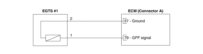
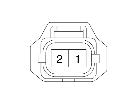
Harness Connector
EGTS #2
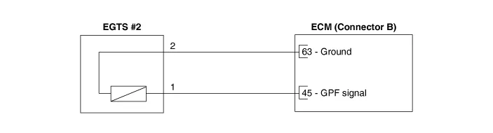
Harness Connector
EGTS #3
Repair procedures
| Inspection |
| 1. |
Turn ignition switch OFF. |
| 2. |
Disconnect the connector of exhaust gas temperature sensors #1/#2/#3. |
| 3. |
Measure resistance between sensor signal terminal and ground terminal. |
| 4. |
Check that the resistance is within the specification. Exhaust Gas Temperature Sensor [EGTS #1, #2, #3 (T3, T4, T5)]
|
| Removal & Installation |
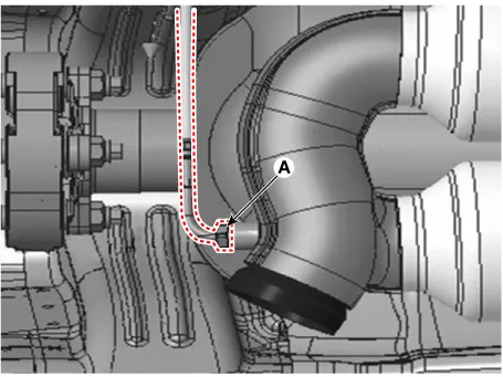
[EGTS #1]
| 1. |
Turn the ignition switch OFF and disconnect the battery negative (-) terminal. |
| 2. |
Remove the floor under cover. |
| 3. |
Disconnect the EGTS connector (A).
|
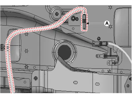
| 4. |
Remove the EGTS (A).
|
| 5. |
Install the sensor in the reverse order of removal.
|

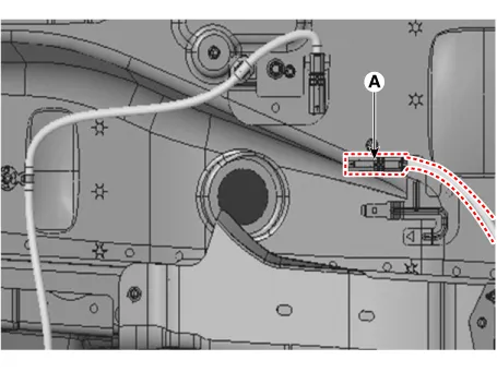
[EGTS #2]
| 1. |
Turn the ignition switch OFF and disconnect the battery negative (-) terminal. |
| 2. |
Remove the floor under cover. |
| 3. |
Disconnect the EGTS connector (A).
|
| 4. |
Remove the EGTS (A).
|
| 5. |
Install the sensor in the reverse order of removal.
|
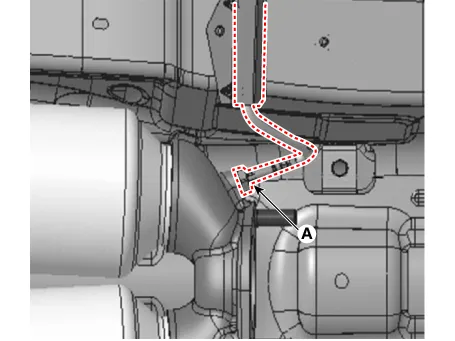
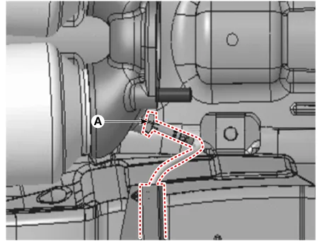
[EGTS #3]
| 1. |
Turn the ignition switch OFF and disconnect the battery negative (-) terminal. |
| 2. |
Remove the floor under cover. |
| 3. |
Disconnect the EGTS connector (A).
|

| 4. |
Remove the EGTS (A).
|
| 5. |
Install the sensor in the reverse order of removal.
|


Other information:
Kia Stinger (CK) 2018-2023 Service Manual: Tail Gate Back Panel
Repair procedures Replacement • Use a plastic panel removal tool to remove interior trim pieces without marring the surface. • Take care not to bend or scratch the trim and panels. 1.Components and components location Component Location 1. Hood assembly Repair procedures Replacement Be careful not to damage the hood and body. When removing and installing the hood, work in a group of two or more.Categories
- Manuals Home
- Kia Stinger Owners Manual
- Kia Stinger Service Manual
- New on site
- Most important about car
