Kia Stinger CK: Engine Control System / ETC (Electronic Throttle Control) System
Specifications
| Specification |
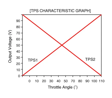
[Throttle Position Sensor (TPS)]
|
Throttle Angle(°) |
Output Voltage(V) [Ref=5V] |
|
|
TPS1 |
TPS2 |
|
|
0 |
0.0 |
5.0 |
|
10 |
0.48 |
4.52 |
|
20 |
0.95 |
4.05 |
|
30 |
1.43 |
3.57 |
|
40 |
1.90 |
3.10 |
|
50 |
2.38 |
2.62 |
|
60 |
2.86 |
2.14 |
|
70 |
3.33 |
1.67 |
|
80 |
3.81 |
1.19 |
|
90 |
4.29 |
0.71 |
|
100 |
4.76 |
0.24 |
|
105 |
5.0 |
0 |
|
C.T (6 - 15°) |
0.29 - 0.71 |
4.29 - 4.71 |
|
W.O.T (93 - 102°) |
4.43 - 4.86 |
0.14 - 0.57 |
[ETC Motor]
|
Item |
Specification |
|
Coil Resistance (Ω) |
1.1 - 1.7 [20°C(68°F)] |
Description and operation
| Description |
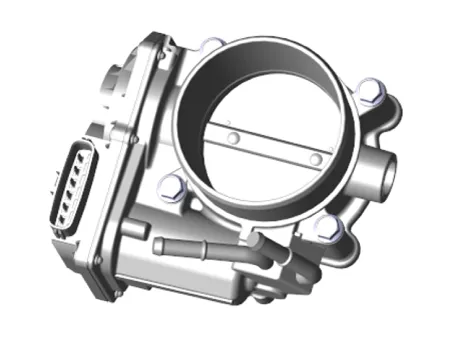
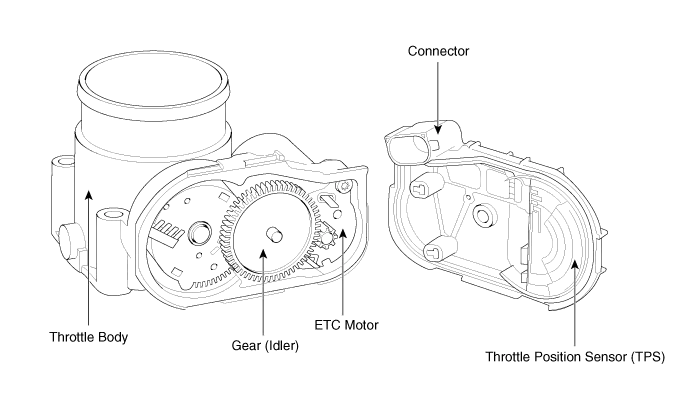
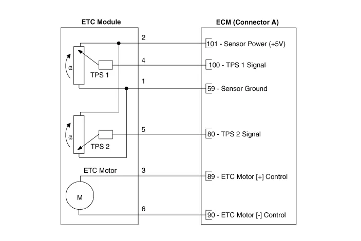
The Electronic Throttle Control (ETC) System consists of a throttle body with an integrated control motor and throttle position sensor (TPS). Unlike the existing mechanical throttle system that controls the throttle valve by using wire cable connected to the accelerator pedal, the ETC system controls the opening and closing of the throttle valve by the ECM with ETC motor according to the APS (Accelerator Position Sensor) signal mounted to electronic accelerator pedal module. The TPS signal is used to provide feedback regarding throttle position to the ECM. Also, the ETC system has the benefit of implementing cruise control function without additional external cruise control modules/cables.
| Schematic Diagram |
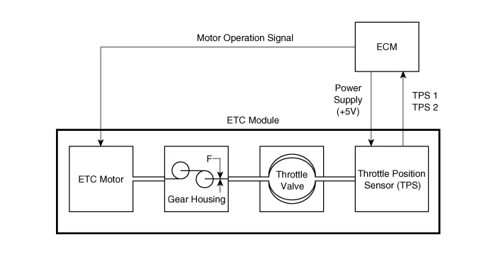
Schematic diagrams
| Circuit Diagram |
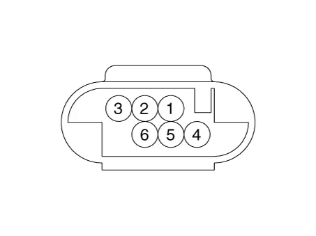
Harness Connector
Repair procedures
| Inspection |
Throttle Position Sensor (TPS)
| 1. |
Connect the KDS on the Data Link Connector (DLC). |
| 2. |
Start the engine and measure the output voltage of TPS 1 and 2 at C.T. and W.O.T.
|
|||||||||||||||||||||||||||||||||||||||||||||||
ETC Motor
| 1. |
Switch "OFF" the ignition. |
| 2. |
Disconnect the ETC module connector. |
| 3. |
Measure resistance between the ETC module terminals 3 and 6. |
| 4. |
Check that the resistance is within the specification.
|
| Removal |
| 1. |
Switch "OFF" the ignition and disconnect the negative (-) battery terminal. |
| 2. |
Remove the alternator assembly. (Refer to Engine Electrical System - "Alternator") |
| 3. |
Remove the intercooler outlet hose & pipe. (Refer to Engine Mechanical System - "Intercooler") |
| 4. |
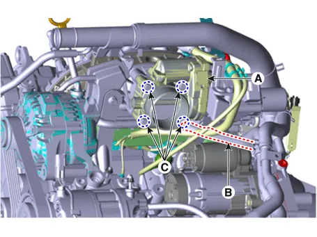
Disconnect the ETC module connector (A). |
| 5. |
Disconnect the coolant hose (B). |
| 6. |
Remove the ETC module from the engine after loosening the installation bolt (C).
|
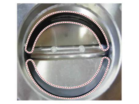
| Cleaning |
| 1. |
Remove the ETC Module. (Refer to Engine Control System - "ETC System") |
| 2. |
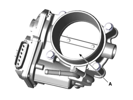
Keep the ETC module plate (A) open.
|
| 3. |
Clean the pollutant in the throttle body with a soft cloth moistened by cleaning fluid.
|

| 4. |
After cleaning, reinstall the ETC module and then perform the ETC module learning procedure. (Refer to Engine Control System - "ETC System" - Adjustment) |
| Installation |
|
| 1. |
Install in the reverse order of removal. |
| Adjustment |
| ETC module learning procedure |
Be sure to perform the ETC module learning procedure when replacing or reinstalling the ETC module.
| 1. |
Wait for 1 minute with the ignition switch ON. |
| 2. |
Start the engine and hold the idle status for 15 minutes. |
| 3. |
Wait for 1 minute with the ignition switch OFF. |
| 4. |
Restart the engine, and check that the idle speed is stable.
|
Troubleshooting
| Fail-Safe Mode |
|
Item |
Fail-Safe |
|
|
ETC Motor |
Throttle valve stuck at 5° |
|
|
TPS |
TPS 1 fault |
ECM looks at TPS2 |
|
TPS 2 fault |
ECM looks at TPS1 |
|
|
TPS 1, 2 fault |
Throttle valve stuck at 5° |
|
|
APS |
APS 1 fault |
ECM looks at APS 2 |
|
APS 2 fault |
ECM looks at APS 1 |
|
|
APS 1, 2 fault |
Throttle valve stuck at 5° |
|
When throttle value is stuck at 7°, engine speed will be limited to below 1,500 rpm and vehicle speed to maximum of 40 - 50 km/h (25 - 31 mph). |


Other information:
Kia Stinger (CK) 2018-2023 Service Manual: P Position Solenoid Valve (ON/OFF)
Specifications Specifications Item Specification Control type ON/OFF Control pressure kpa (kgf/cm², psi) 539.36 (5.5, 78.23) Current (mA) 0 - 600 Coil resistance (Ω) 10.5 ± 0.5 Components and components location Components Location 1.Flow diagram Flow Diagram Repair procedures Oil and filter replacement • Prolonged and repeated contact with mineral oil will result in the removal of natural fats from the skin, leading to dryness, irritation and dermatitis.Categories
- Manuals Home
- Kia Stinger Owners Manual
- Kia Stinger Service Manual
- New on site
- Most important about car
