Kia Stinger CK: Driving your vehicle / ISG (Idle Stop and Go) system
Contents:
Your vehicle may be equipped with the ISG system, which reduces fuel consumption by automatically shutting down the engine, when the vehicle is at a standstill. (For example : red light, stop sign and traffic jam)
The engine starts automatically as soon as the starting conditions are met.
The ISG system is ON whenever the engine is running.
✽ NOTICE
When the engine automatically starts by the ISG system, some warning lights (ABS, ESC, ESC OFF, EPS or Parking brake warning light) may turn on for a few seconds. This happens because of low battery voltage. It does not mean the system has malfunctioned.
Auto stop ➤
Auto start ➤
Condition of ISG system operation
The ISG system will operate under the following condition:
- The driver’s seat belt is fastened.
- The driver’s door and engine hood are closed.
- The brake vacuum pressure is adequate.
- The battery is sufficiently charged.
- The outside temperature is between 14°F to 95°F (-10°C to 35°C).
- The engine coolant temperature is not too low.
✽ NOTICE
- If the ISG system does not meet the operation condition, the ISG system is deactivated. The light on the ISG OFF button will illuminate and a message “Auto Stop conditions not met” will appear on the LCD display.
- If the light or notice comes on continuously, please check the operation condition.
ISG system deactivation
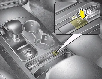
- If you wish to deactivate the ISG system, press the ISG OFF button (1). The light on the ISG OFF button will illuminate.
- If you press the ISG OFF button again, the system will be activated and the light on the ISG OFF button will turn off.
ISG system malfunction ➤


Other information:
Kia Stinger (CK) 2018-2023 Owner's Manual: Front Door Side Weatherstrip
Repair procedures Replacement 1. Loosen the front door checker (A) mounting bolt. Tightening torque : 19.6 - 29.4 N·m (2.0 - 3.0 Kgf·m, 14.5 - 21.7 lb·ft) 2. Detach the clips, then remove the front door side weatherstrip (A). Tightening torque : 19.Kia Stinger (CK) 2018-2023 Owner's Manual: Installing a Child Restraint System (CRS)
After selecting a proper child seat for your child, check to make sure it fits properly in your vehicle. Follow the instructions provided by the manufacturer when installing the child seat. Note these general steps when installing the seat to your vehicle: Properly secure the child restraint to the vehicle. All child restraints must be secured to the vehicle with the lap part of a lap/shoulder belt or with the LATCH system.Categories
- Manuals Home
- Kia Stinger Owners Manual
- Kia Stinger Service Manual
- New on site
- Most important about car
Contents
