Kia Stinger CK: Tire Pressure Monitoring System / TPMS Sensor
Description and operation
| Description |
| 1. |
Function
|
| 2. |
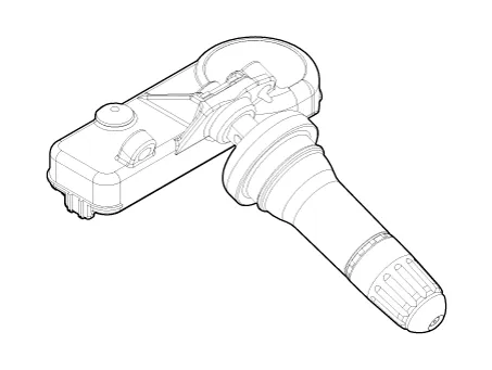
Structure and features
|
TPMS Automatic Location Learning
| • |
Wheel angular velocity of wheels are different from each other in the following cases: |
| 1) |
Slip for each axis occurs differently. |
| 2) |
Rotation radius (the radius of curve) for each wheel is different. |
| 3) |
Tire wear, internal pressure, tire specifications, etc. for each tire are different. |
| • |
TPMS sensor is transmitted to RF signal at only specific phase (the angle of the tire) in the learning mode. |
| • |
TPMS receiver checks each tire phase (tire angle) information on receiving RF signals from the sensor. |
| • |
Every time RF signals from sensor IDs 1, 2, 3, and 4 are received, the ID with the highest correlation among the phase of each collected wheel is transmitted. (In other words, each time RF signal is received, the phase of the tire is transmitted to the most constant wheel.) |
| • |
TPMS sensor transmits the RF signal at intervals of 16 seconds in the learning mode. |
| • |
After stopping or parking for more than 19 minutes, automatic learning function in every driving position is performed. |
| • |
The sensor is converted to Parking Mode when stopped or parked for more than 15 minutes. When acceleration of over 4g (15-20km/h) is detected in Parking Mode, it is converted to First Block Mode. |
Repair procedures
| Removal |
| 1. |
Remove the tire. (Refer to Tires/Wheels - "Tire") |
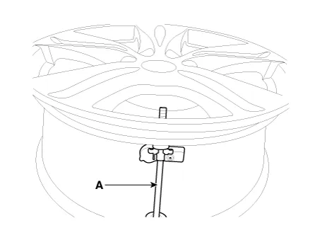
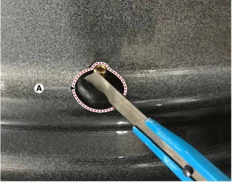
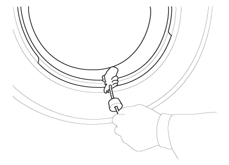
| 2. |
Remove the screw with torx driver (A).
|

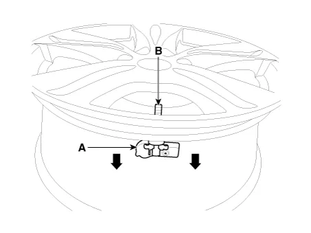
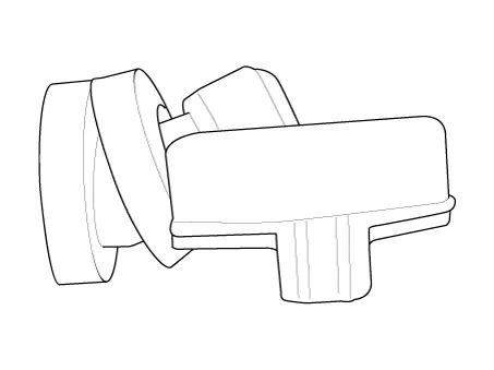
| 3. |
Remove the sensor body (A) from the valve (B) in the direction of the arrow.
|
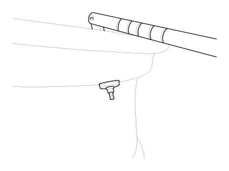
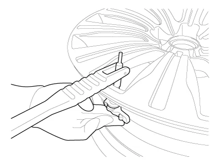
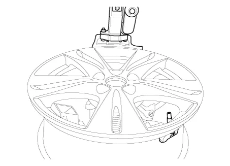
| 4. |
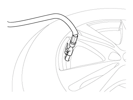
Use the valve mounting tool to pull out the valve until it is entirely out of the lower hole.
|

| 5. |
Apply lubricant to the surface of the valve, and then mount it through the valve hole of the wheel.
|
| 6. |
Apply soapy water or lubricant to the upper/lower bead section of the tire.
|
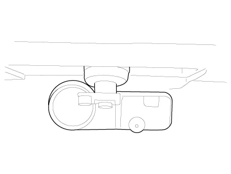
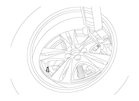
| 7. |
In order to mount lower the beads, place the TPMS sensor at 5 o'clock, starting from the head of the tire replacement equipment.
|
| 8. |
Rotate the rim clockwise and press tire towards 3 o'clock to mount the lower beads.
|
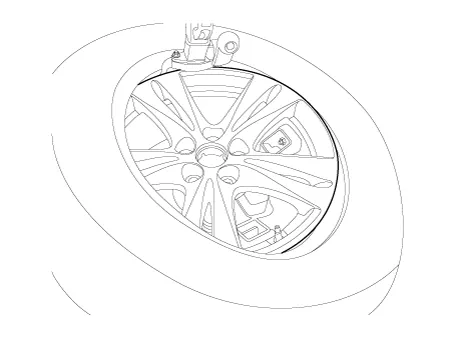
| 9. |
In order to mount the upper beads, press the tire towards 3 o'clock and turn the rim clockwise.
|
| 10. |
Inject air into the tire until the beads are in the correct position.
|
| 11. |
Adjust the tire pressure according to the recommended tire pressure for the vehicle. |
| 12. |
If the TPMS sensor malfunctions, you must perform TPMS sensor learning. Replace any faulty sensors and perform TPMS sensor learning. |
| Inspection |
Test procedures after installing TPMS sensor
| 1. |
The sealing washer should be compressed on the outside rim of the hole. |
| 2. |
The lower part of the valve should be located in a specified place (no metal brackets). |
| 3. |
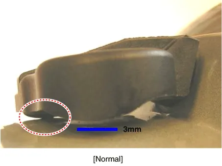
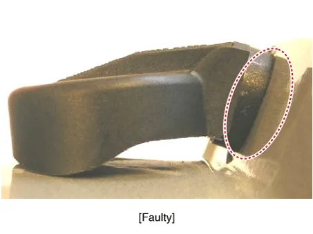
The housing should contact at least one or more points of the rim surface. |
| 4. |
The rim of the housing mounting height shall not exceed the height of the chin.
|
| Diagnostic Procedure Using a Diagnostic Instrument |
The following section describes how to diagnose faults using a diagnostic instrument.
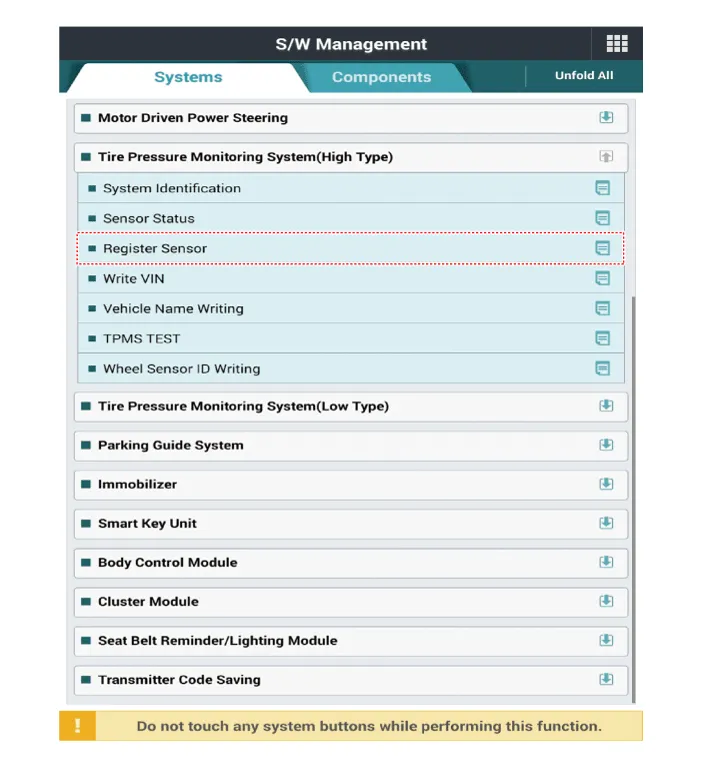
| 1. |
Connect the diagnostic instrument to the self-diagnostic connector (16-pin) beneath the crash pad on the side of driver's seat, and then turn on the ignition to activate the diagnostic instrument. |
| 2. |
In the KDS Vehicle Type Selection menu, select "Vehicle Type" and "TPMS" System, and then opt for "OK." |
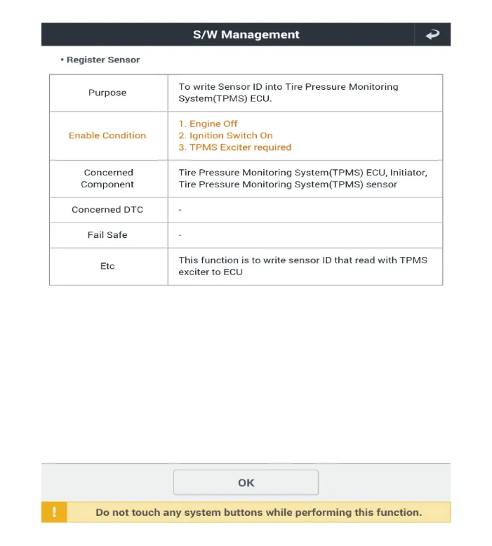
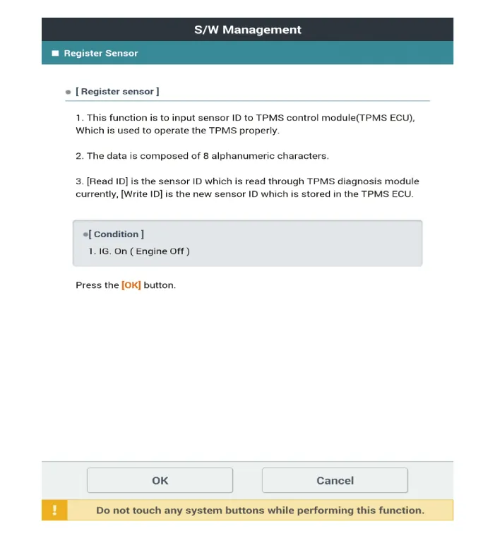
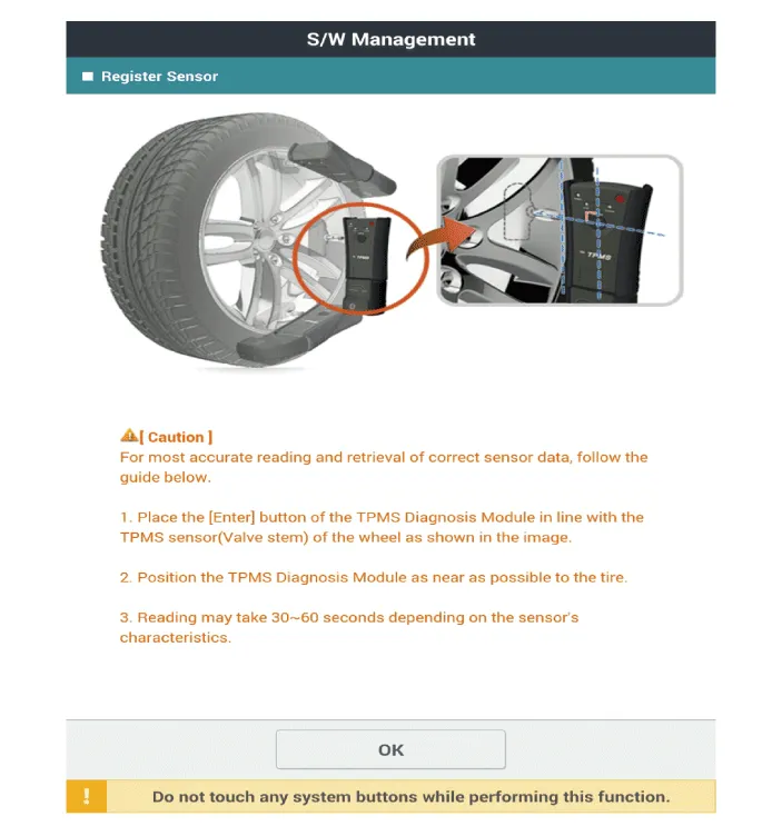
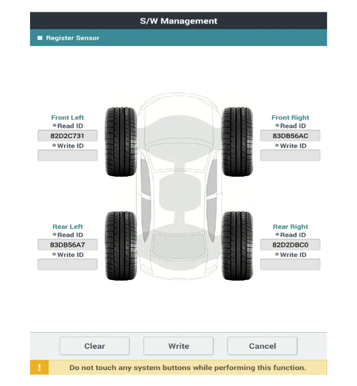
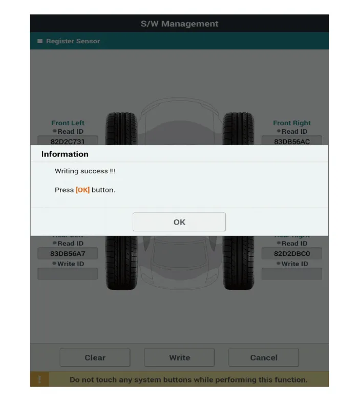
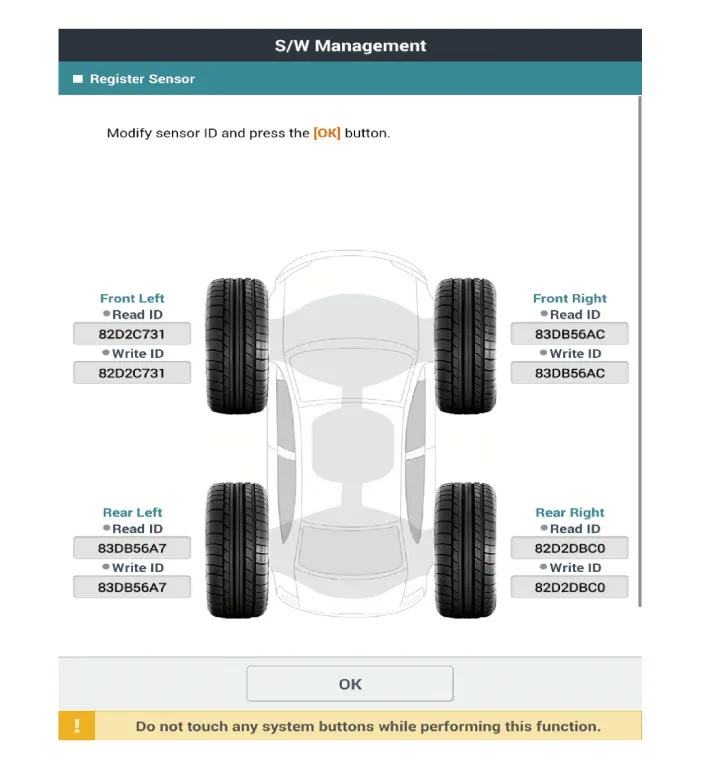
[Register Sensor Method]
|
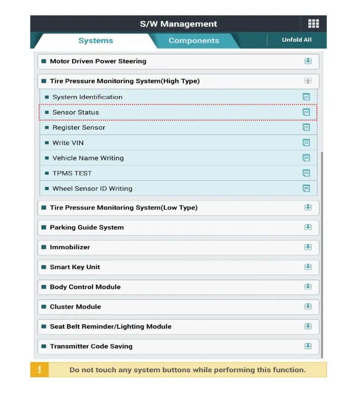
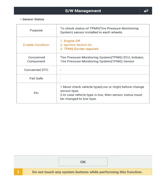
[Sensor Status Method]
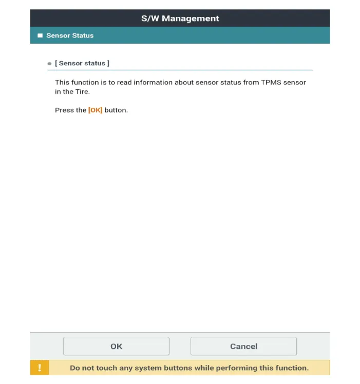
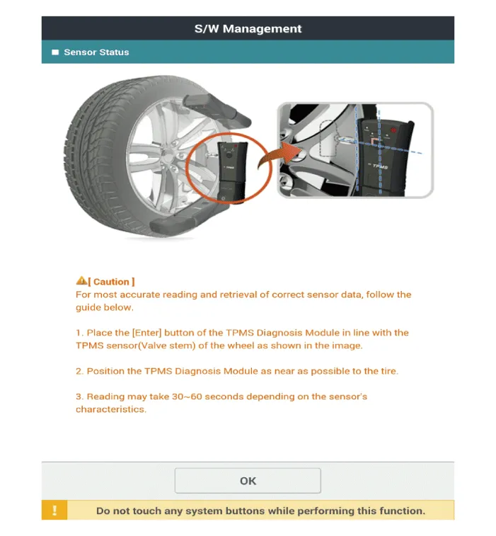
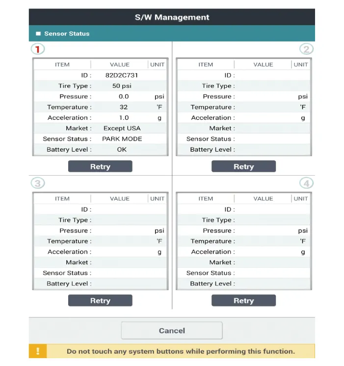
|


Other information:
Kia Stinger (CK) 2018-2023 Service Manual: Delivery Pipe
Repair procedures Removal 1. Release the residual pressure in fuel line. (Refer to the Fuel Delivery System - "Release Residual Pressure in Fuel Line") 2. Switch "OFF" the ignition and disconnect the negative (-) battery terminal. 3. Remove the intake manifold.Kia Stinger (CK) 2018-2023 Service Manual: Damper Clutch Control Solenoid Valve (D/C_VFS)
Specifications Specifications Item Specification Control type N/L (Normal Low) Control pressure kpa (kgf/cm², psi) 0 - 519.75 (0 - 5.3, 0 - 75.38) Current (mA) 0 - 850 Coil resistance (Ω) 5.Categories
- Manuals Home
- Kia Stinger Owners Manual
- Kia Stinger Service Manual
- New on site
- Most important about car
