Kia Stinger CK: Drive Belt System / Drive Belt
Repair procedures
| Removal |
| 1. |
Remove the engine room front under cover. (Refer to Engine and Transmission Assembly - "Engine Room Under Cover") |
| 2. |
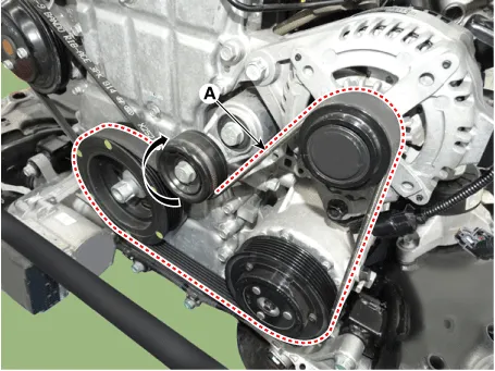
For release the tension, turn the drive belt tensioner (A) counterclockwise then remove the drive belt (B).
|
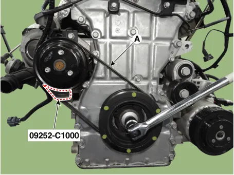
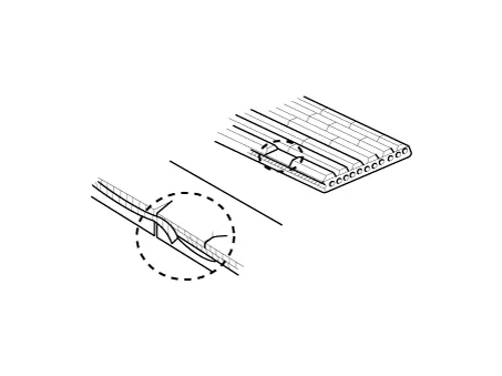
| 3. |
Remove the water pump belt.
|
| Inspection |
| 1. |
Visually check the belt for excessive wear, frayed cords etc. If any defect has been found, replace the drive belt.
|

| Installation |
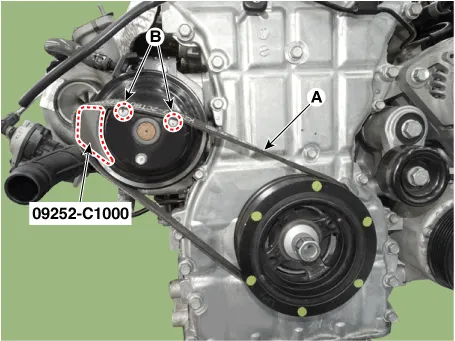
| 1. |
Install the water pump belt.
|
| 2. |
For release the tension, turn the drive belt tensioner (A) counterclockwise then install the drive belt (B).
|
| 3. |
Install the other parts in the reverse order of removal. |


Other information:
Kia Stinger (CK) 2018-2023 Service Manual: Fluid (ATF)
Repair procedures Automatic Transmission Fluid (ATF) Level Check 1. Start the engine to warm up the ATF. Do not step on the brake and accelerator simultaneously to warm up the ATF. 2.Kia Stinger (CK) 2018-2023 Service Manual: Engine compartment fuse replacement
1. Turn the ignition switch and all other switches off. 2. Remove the fuse panel cover by pressing the tab and pulling the cover up. When the blade type fuse is disconnected, remove it by using the clip designed for changing fuses located in the engine compartment fuse box. Upon removal, securely insert reserve fuse of the same rating. 3. Check the removed fuse; replace it if it is blown.Categories
- Manuals Home
- Kia Stinger Owners Manual
- Kia Stinger Service Manual
- New on site
- Most important about car
