
Kia Stinger CK: Parking Brake System / Electric Parking Brake (EPB)
Description and operation
| Description |
Description of EPB
The EPB is an electronic parking brake. The EPB is different from existing parking systems which operated with the brake pedal or the lever type. The EPB system sends the signal to the ECU when a driver operates the EPB switch. The ECU operates the EPB actuator composed with motor gears. EPB has several functions.
| – |
Static apply |
| – |
Emergency braking function by hydraulic brake malfunction |
| – |
Auto apply |
| EPB Function |
| 1. |
Switch Operation at Stationary Condition (Static Park)
|
| 2. |
Switch Release at Stationary Condition (Static Release)
|
| 3. |
Dynamic Emergency Braking (Dynamic Braking)
|
| 4. |
Automatic Application of EPB Force (Auto Apply)
|
| 5. |
Automatic Release of EPB Force (Drive Away Release)
|
| 6. |
Reapplication of EPB Force When Vehicle Moves Downwards (Roll Away Reclamp)
|
| 7. |
P to X (Automatic Release of EPB Force for Gear Shifting) When moving the gearshift lever from the P or N position to the D or R position, the parking brake will be automatically released. However, it will be possible only with the engine ON and the brake pedal pressed, in order to secure safety for automatic release. |
| 8. |
Auto Hold Auto hold helps keep vehicle in a stop condition by applying hydraulic brake at a stop.
[Abnormal conversion case]
|
| Warning Lamp |



| 1. |
EPB warning lamp EPB warning lamp indicates the EPB cut and malfunction. EPB warning lamp comes ON below cases.
|
| 2. |
2. AUTO HOLD lamp / AUTO HOLD function lamp
|
Components and components location
| Components |
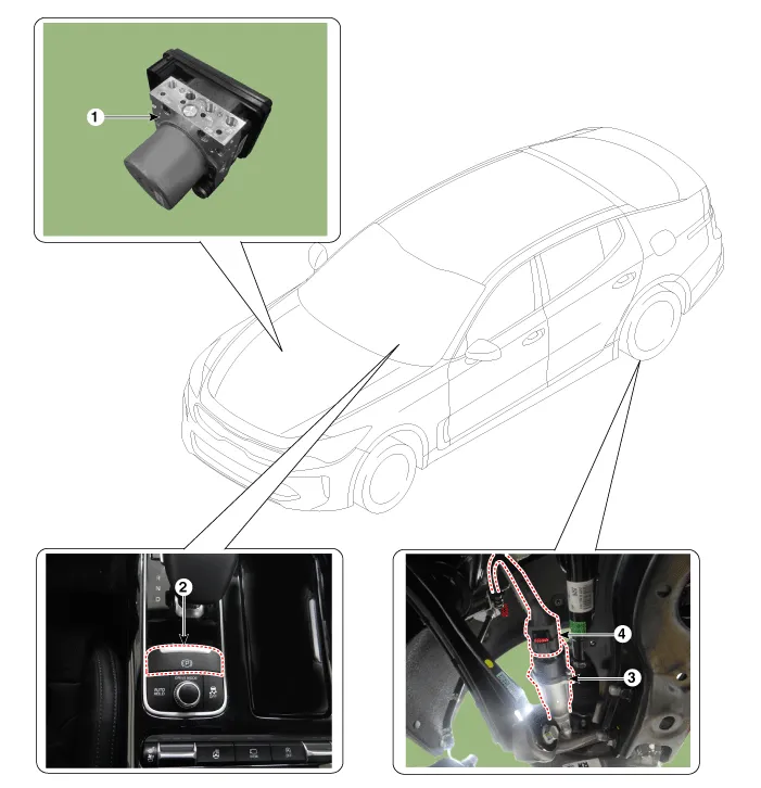
| 1. HECU module 2. EPB switch |
3. Electric parking brake (EPB)
actuator 4. Electric parking brake (EPB) actuator extension wire |
Repair procedures
| Removal |
[EPB Type]
| 1. |
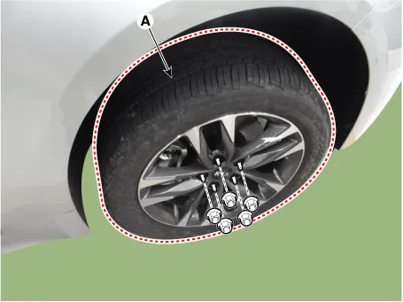
Remove wheel nuts, wheel and tire (A) from hub.
|

| 2. |
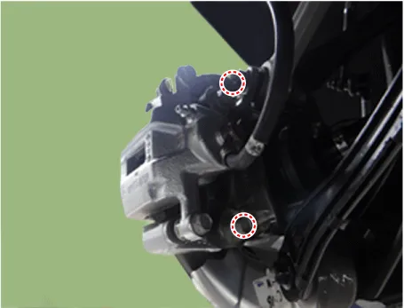
Loosen the brake caliper guide bolts and then remove the brake caliper.
|
| 3. |
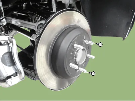
Loosen the brake disc screw and then remove the brake disc.
|
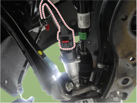
| 4. |
Disconnect the EPB actuator connector.
|
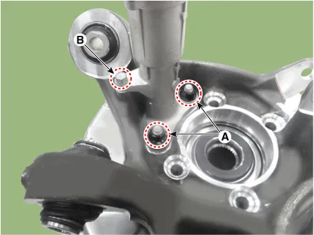
| 5. |
Loosen the EPB actuator (A) nuts and bolt (B).
|
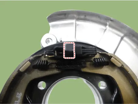
| 6. |
Remove the pin.
|
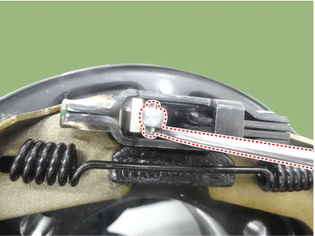
| 7. |
Using the driver, push the rod and then remove the EPB actuator.
|
| 8. |
Install in the reverse order of removal. |


Other information:
Kia Stinger (CK) 2018-2023 Service Manual: Inhibitor Switch
Specifications Specifications Item Specification Output type PWM Power supply (V) 5 Components and components location Components Location 1. Inhibitor switch 2. Manual control lever Schematic diagrams Circuit Diagram Repair procedures Inspection Inspect the connector thoroughly for looseness, poor connection, bending, corrosion, contamination, deformation, or damage.Kia Stinger (CK) 2018-2023 Service Manual: Steering Gear box
Components and components location Components 1. Tie rod end 2. R-MDPS motor Repair procedures Removal 1. Remove wheel nuts, front wheel and tire (A) from hub. Tightening torque : 107.9 - 127.5 N·m (11.0 - 13.0 kgf·m, 79.6 - 94.0 lb·ft) Be careful not to damage the wheel bolts when removing the wheel and tire (A).Categories
- Manuals Home
- Kia Stinger Owners Manual
- Kia Stinger Service Manual
- New on site
- Most important about car
