Kia Stinger CK: Front Suspension System / Front Strut Assembly
Components and components location
| Components |
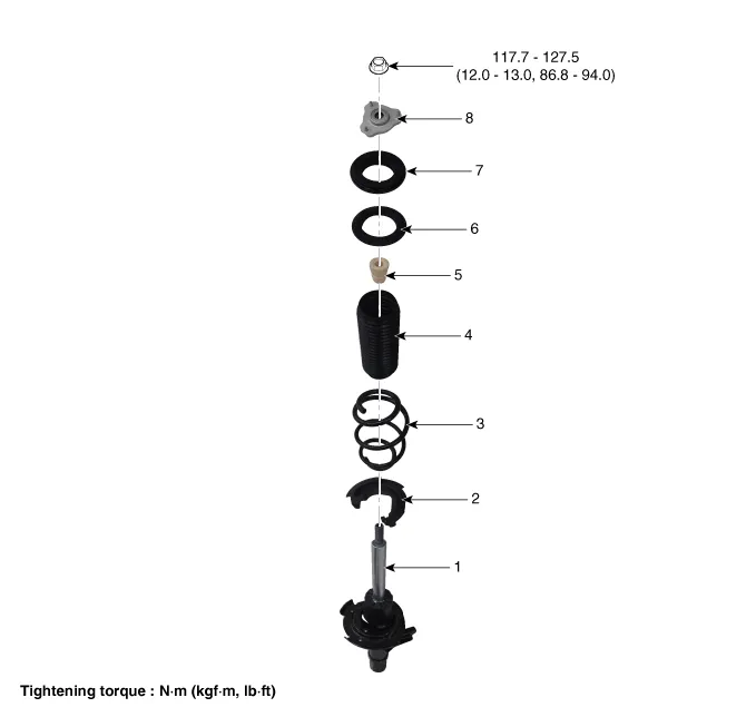
| 1. Shock absorber 2. Spring lower pad 3. Coil spring 4. Dust cover 5. Bumper stopper |
6. Spring upper cover 7. Strut bearing 8. Insulator assembly 9. Lock nut |
Repair procedures
| Removal |
[2WD]
| 1. |
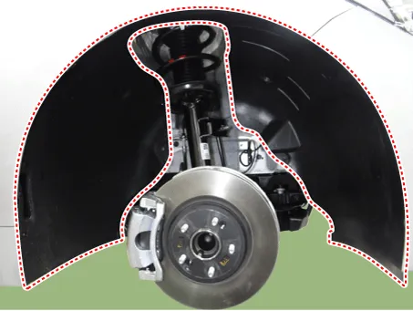
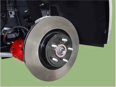
Remove wheel nuts, front wheel and tire (A) from hub.
|


| 2. |
Remove the front wheel guard.
|
| 3. |
Remove the front stabilizer bar. (Refer to Suspension System - "Front Stabilizer Bar") |
| 4. |
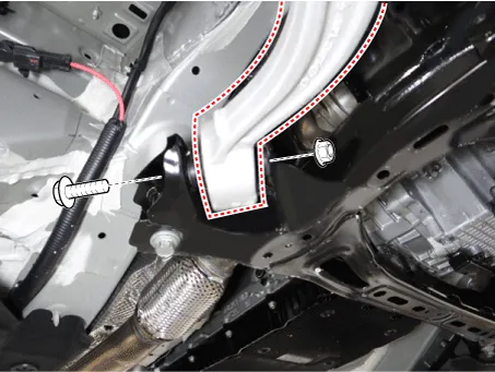
Remove the engine room side cover. D 2.2 R VGT (Refer to Engine Mechanical System - "Engine Room Under cover") G 2.0 T-GDI THETA II (Refer to Engine Mechanical System - "Engine Room Under cover") G 3.3 T-GDI LAMBDA II (Refer to Engine Mechanical System - "Engine Room Under cover") |
| 5. |
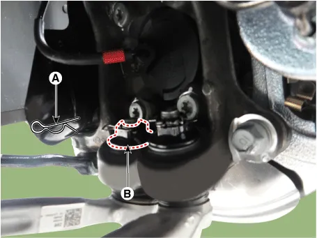
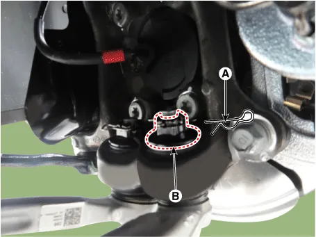
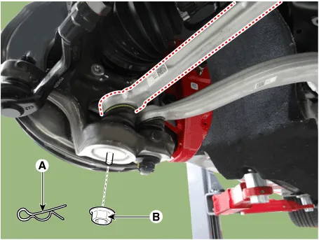
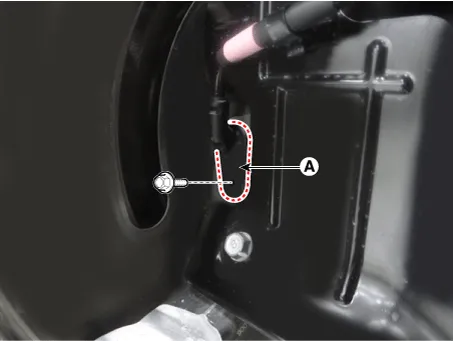
Loosen the lateral arm pin (A) and nut (B).
|
| 6. |
Loosen the compression arm pin (A) and nut (B).
|
| 7. |
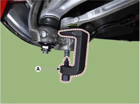
Loosen the compression arm bolt & nut from the subframe.
|
| 8. |
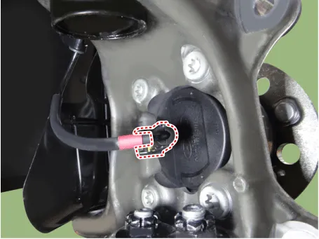
Disonnec the wheel speed sensor connector.
|
| 9. |
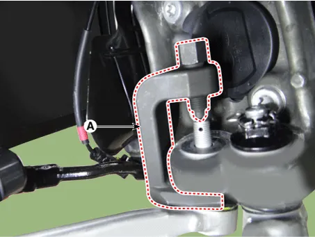
Remove the lateral arm by using the ball joint remover (A).
|
| 10. |
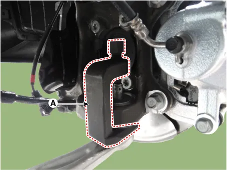
Remove the compression arm by using the ball joint remover (A).
|
| 11. |
Remove the brake caliper. (Refer to Brake System - "Front Disc Brake") |
| 12. |
Remove the tie rod end nut.
|
| 13. |
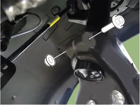
Remove the knuckle by using the ball joint remover (A).
|
| 14. |
Loosen the wheel speed sensor bracket bolt and then remove the wheel speed sensor bracket.
|
| 15. |
Loosen the brake caliper hose bracket bolt.
|
| 16. |
Loosen the knuckle upper bolt & nut.
|
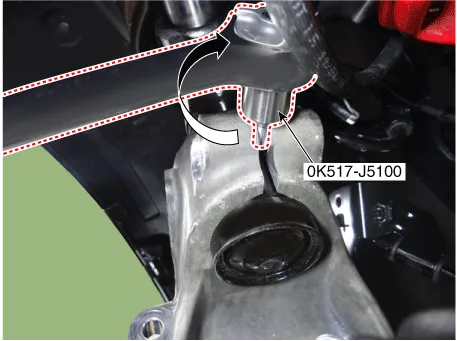
| 17. |
Remove the knuckle by using the SST (0K517-J5100).
|
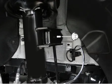
| 18. |
Loosen the shock absorber upper nuts and then remove the shock absorber.
|
| 19. |
Install in the reverse order of removal.
|
| 20. |
Check the front alignment. (Refer to Suspension System - "Alignment") |
| [AWD] |
| 1. |
Remove wheel nuts, front wheel and tire (A) from front hub.
|
| 2. |
Remove the brake caliper. (Refer to Brake System - "Front Disc Brake") |
| 3. |
Loosen the nut and then separate the stabilizer link from the front shock absorber.
|
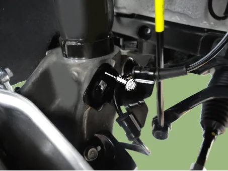
| 4. |
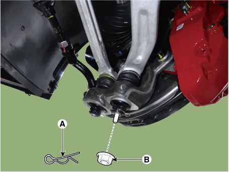
Loosen the lateral arm pin (A) and nut (B).
|
| 5. |
Remove the lateral arm by using the ball joint remover (A).
|
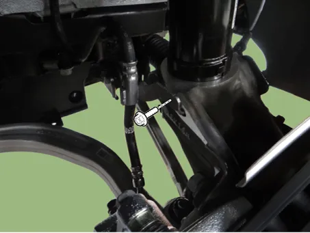
| 6. |
Loosen the compression arm pin (A) and nut (B).
|
| 7. |
Remove the compression arm by using the ball joint remover (A).
|

| 8. |
Remove the tie rod end nut.
|
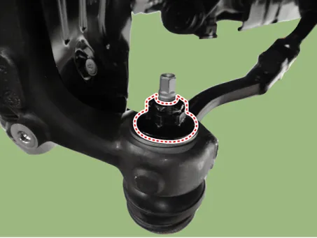
| 9. |
Remove the knuckle by using the ball joint remover (A).
|
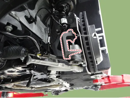
| 10. |
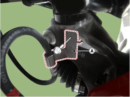
Remove the brake hose bracket (A).
|
| 11. |
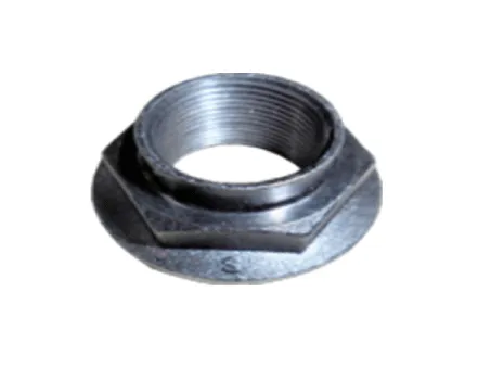
By hammering on a chisel, unlock the driveshaft lock hub nut caulking.
|
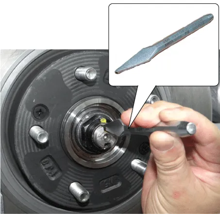
| 12. |
Loosen the caulking nut (A) and then separate the hub assembly from the drive shaft.
|
| 13. |
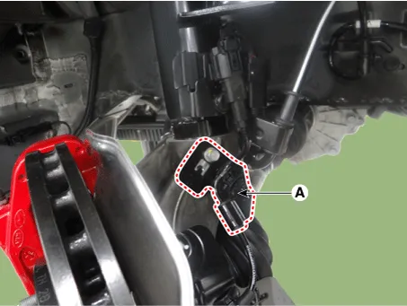
Loosen the wheel speed sensor bolt (A) and then disconnect the wheel speed sensor.
|
| 14. |
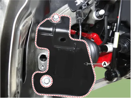
Remove the brake cooling cover (A).
|
| 15. |
Remove the wheel speed sensor bracket (A).
|
| 16. |
Loosen the knuckle upper bolt & nut.
|
| 17. |
Remove the knuckle by using the SST (0K517-J5100).
|
| 18. |
Loosen the shock absorber upper nuts and then remove the shock absorber.
|
| 19. |
Install in the reverse order of removal.
|
| 20. |
Check the front alignment. (Refer to Suspension System - "Alignment") |
| Disassembly |
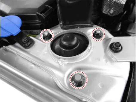
| 1. |
Remove the front shock absorber cover. |
| 2. |
Compress the coil spring (A) with a strut spring compressor. Do not compress the spring excessively.
|
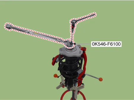
| 3. |
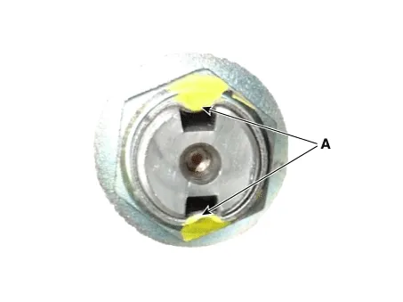
Using the SST(0K546-F6100), loosen the lock nut.
|
| 4. |
Gradually turn the bolt on the spring compressor to slowly release the tension from the spring. Then, disconnect the components. |
| 5. |
Install in the reverse order of removal. |
| Inspection |
| 1. |
Check the strut insulator for wear or damage. |
| 2. |
Check rubber parts for damage or deterioration. |
| 3. |
Compress and extend the piston rod and check that there is no abnormal resistance or unusual sound during operation. |


Other information:
First secure the child restraint with the LATCH lower anchors or the seat belt. If the child restraint manufacturer recommends that the top tether strap be attached, attach and tighten the top tether strap to the top tether strap anchor. Child restraint hook holders are located on the back of the rear seatbacks. WARNING Take the following precautions when installing the tether strap: Read and follow all installation instructions provided with your child restraint system.Kia Stinger (CK) 2018-2023 Service Manual: Headlamp Leveling Switch (Manual)
Schematic diagrams Circuit Diagram Repair procedures Removal 1. Disconnect the negative (-) battery terminal. 2. Remove the crash pad lower panel. (Refer to Body - "Crash Pad Lower Panel") 3. Remove the crash pad garnish [LH] (A) after loosening the mounting screw.Categories
- Manuals Home
- Kia Stinger Owners Manual
- Kia Stinger Service Manual
- New on site
- Most important about car
