Kia Stinger CK: Fuel Filler Door / Fuel Filler Door Open Switch
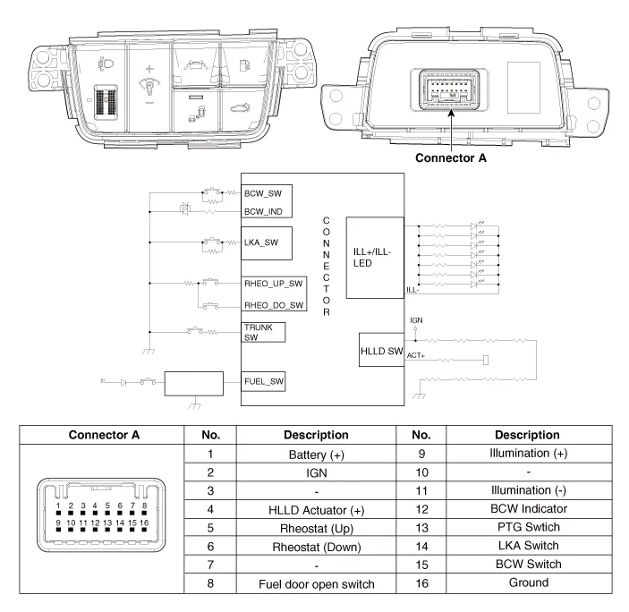
Components and components location
| Components |
Repair procedures
| Removal |
| 1. |
Disconnect the negative (-) battery terminal. |
| 2. |
Remove the crash pad lower panel. (Refer to Body - "Crash Pad Lower Panel") |
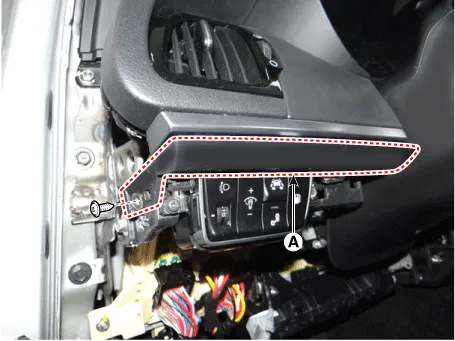
| 3. |
Remove the crash pad garnish [LH] (A) after loosening the mounting screw.
|
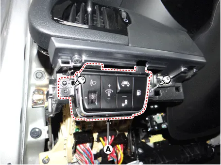
| 4. |
Remove the side crash pad switch (A) after loosening the mounting screws.
|
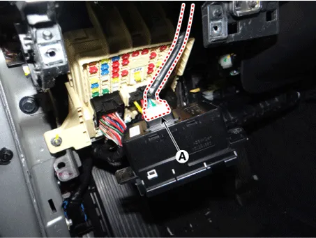
| 5. |
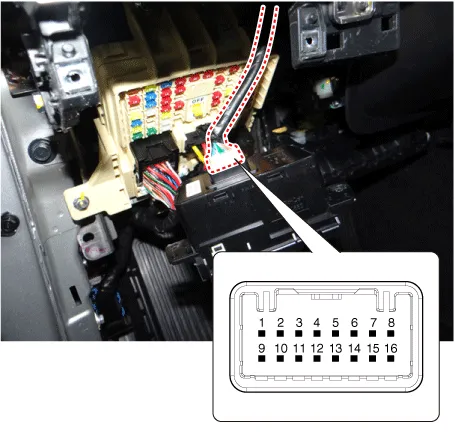
Disconnect the side crash pad switch connector (A).
|
| Installation |
| 1. |
Connect the side crash pad switch connector. |
| 2. |
Install the side crash pad switch. |
| 3. |
Install the crash pad garnish [LH]. |
| 4. |
Install the crash pad lower panel. |
| 5. |
Connect the negative (-) battery terminal. |
| Inspection |
| 1. |
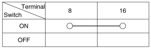
Check for continuity between the terminals. If there is an abnormality, replace the switch.
|


Other information:
Kia Stinger (CK) 2018-2023 Service Manual: Engine Oil and Filter
Repair procedures Inspection [Theta-II 2.0 T-GDI / Lambda-II 3.3 T-GDI] Engine Oil Level Be sure that the vehicle is on level ground. 1. Warm up and stop the engine, and then wait for 5 minutes. 2. Turn the engine off and wait for a few minutes (about 5 minutes) for the oil to return to the oil pan.Kia Stinger (CK) 2018-2023 Service Manual: Tire Pressure Monitoring System
Components and components location Components 1. IBU(TPMS) 2. TPMS sensor (FL) 3. TPMS sensor (RL) 4. TPMS sensor (RR) 5. TPMS sensor (FR) Description and operation Description TREAD Lamp – Tire Under Inflation / Leak Warning. 1. Turn on condition • When tire pressure is below allowed threshold • When rapid leak is detected by the sensor.Categories
- Manuals Home
- Kia Stinger Owners Manual
- Kia Stinger Service Manual
- New on site
- Most important about car
